
An instruction specifies is a set of bit specifying an operation - PowerPoint PPT Presentation
1 / 6
Title:
An instruction specifies is a set of bit specifying an operation
Description:
These facts allow design of a gated latch with control signal G ... When C is low, first latch gates data on D, second does nothing ... – PowerPoint PPT presentation
Number of Views:36
Avg rating:3.0/5.0
Title: An instruction specifies is a set of bit specifying an operation
1
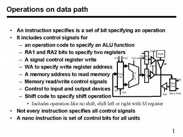
Operations on data path
- An instruction specifies is a set of bit
specifying an operation - It includes control signals for
- an operation code to specify an ALU function
- RA1 and RA2 bits to specify two registers
- A signal control register write
- WA to specify write register address
- A memory address to read memory
- Memory read/write control signals
- Control to input and output devices
- Shift code to specify shift operation
- Includes operation like no shift, shift left or
right with M register - Not every instruction specifies all control
signals - A nano instruction is set of control bits for all
units
2
Register file design
- We will design an eight register file with 4-bit
wide registers - A single 4-bit register and its abstraction are
shown below - We have to use eight such registers to make an
eight register file
3
Reading circuit
- To read any register, we need to multiplex the
outputs - A 3-bit address, RA, specifies which register is
to be read - The address is decoded to get the enable signal
if using tri-state
4
Adding write control to register file
- To write any register, we need register address
and a write signal - A 3-bit write address is decoded if write signal
is present - One of the eight registers gets a LD signal from
decoder
5
RS-latches and gated latch a reminder
- RS latch can act as a storage device
- If R 1 and S 0, then Q goes to 0 and P goes
to 1 - If R 0 and S 1, then P goes to 0 and Q goes
to 1 - When R 0 and S 0, then P and Q remain where
they are - Both R and S 1 is a bad idea (for us) at the
same time - These facts allow design of a gated latch with
control signal G - G 0 means no writing, G 1 allows writing of
input D
6
Edge-Triggered D-Flip-Flop another reminder
- Managing timing based on levels of signals is
hard - We define a precise point in time when data gets
stored - In an edge-Triggered flip-flop data is written on
a clock edge - This is achieved by connecting two gated latches
as below - When C is low, first latch gates data on D,
second does nothing - When C goes high, the second latch latches Q of
the first latch - A LD control can be added to load the new data or
retain old data - D-latches also have a reset input to set Q output
to zero
Clock
Recommended
CrystalGraphics Presentations


