
I dont care - PowerPoint PPT Presentation
Title:
I dont care
Description:
If some outputs aren't used in the rest of the circuit. ... notation means that input combinations wxyz = 0111, 1010 and 1101 (corresponding ... – PowerPoint PPT presentation
Number of Views:98
Avg rating:3.0/5.0
Title: I dont care
1
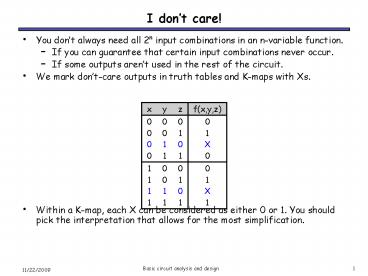
I dont care!
- You dont always need all 2n input combinations
in an n-variable function. - If you can guarantee that certain input
combinations never occur. - If some outputs arent used in the rest of the
circuit. - We mark dont-care outputs in truth tables and
K-maps with Xs. - Within a K-map, each X can be considered as
either 0 or 1. You should pick the interpretation
that allows for the most simplification.
2
Example Seven Segment Display
Input digit encoded as 4 bits ABCD
Table for e
b
Assumption Input represents a legal digit (0-9)
e
d
CD BD
3
Example Seven Segment Display
a
Table for a
f
b
g
e
c
d
A C BD BD
The expression in book (p 110) is different
because it assumes 0 for illegal inputs
ACABDBCDABC
4
Practice K-map 3
- Find a MSP for
- f(w,x,y,z) ?m(0,2,4,5,8,14,15), d(w,x,y,z)
?m(7,10,13) - This notation means that input combinations wxyz
0111, 1010 and 1101 (corresponding to minterms
m7, m10 and m13) are unused.
5
Solutions for practice K-map 3
- Find a MSP for
- f(w,x,y,z) ?m(0,2,4,5,8,14,15), d(w,x,y,z)
?m(7,10,13)
All prime implicants are circled. We can treat
Xs as 1s if we want, so the red group includes
two Xs, and the light blue group includes one
X. The only essential prime implicant is xz.
The red group is not essential because the
minterms in it also appear in other groups. The
MSP is xz wxy wxy. It turns out the red
group is redundant we can cover all of the
minterms in the map without it.
6
K-map Summary
- K-maps are an alternative to algebra for
simplifying expressions. - The result is a minimal sum of products, which
leads to a minimal two-level circuit. - Its easy to handle dont-care conditions.
- K-maps are really only good for manual
simplification of small expressions... but thats
good enough for CS231! - Things to keep in mind
- Remember the correct order of minterms on the
K-map. - When grouping, you can wrap around all sides of
the K-map, and your groups can overlap. - Make as few rectangles as possible, but make each
of them as large as possible. This leads to
fewer, but simpler, product terms. - There may be more than one valid solution.
7
Basic circuit analysis and design
- We have learned all the prerequisite material
- Truth tables and Boolean expressions describe
functions. - Expressions can be converted into hardware
circuits. - Boolean algebra and K-maps help simplify
expressions and circuits. - Now, let us put all of these foundations to good
use, to analyze and design some larger circuits.
8
Circuit analysis
- Circuit analysis involves figuring out what some
circuit does. - Every circuit computes some function, which can
be described with Boolean expressions or truth
tables. - So, the goal is to find an expression or truth
table for the circuit. - The first thing to do is figure out what the
inputs and outputs of the overall circuit are. - This step is often overlooked!
- The example circuit here has three inputs x, y, z
and one output f.
9
Write algebraic expressions...
- Next, write expressions for the outputs of each
individual gate, based on that gates inputs. - Start from the inputs and work towards the
outputs. - It might help to do some algebraic simplification
along the way. - Here is the example again.
- We did a little simplification for the top AND
gate. - You can see the circuit computes f(x,y,z) xz
yz xyz
10
...or make a truth table
- Its also possible to find a truth table directly
from the circuit. - Once you know the number of inputs and outputs,
list all the possible input combinations in your
truth table. - A circuit with n inputs should have a truth table
with 2n rows. - Our example has three inputs, so the truth table
will have 23 8 rows. All the possible input
combinations are shown.
11
Simulating the circuit
- Then you can simulate the circuit, either by hand
or with a program like LogicWorks, to find the
output for each possible combination of inputs. - For example, when xyz 101, the gate outputs
would be as shown below. - Use truth tables for AND, OR and NOT to find the
gate outputs. - For the final output, we find that f(1,0,1) 1.
12
Finishing the truth table
- Doing the same thing for all the other input
combinations yields the complete truth table. - This is simple, but tedious.
13
Expressions and truth tables
- Remember that if you already have a Boolean
expression, you can use that to easily make a
truth table. - For example, since we already found that the
circuit computes the function f(x,y,z) xz yz
xyz, we can use that to fill in a table - We show intermediate columns for the terms xz,
yz and xyz. - Then, f is obtained by just ORing the
intermediate columns.
14
Truth tables and expressions
- The opposite is also true its easy to come up
with an expression if you already have a truth
table. - We saw that you can quickly convert a truth table
into a sum of minterms expression. The minterms
correspond to the truth table rows where the
output is 1. - You can then simplify this sum of minterms if
desiredusing a K-map, for example.
f(x,y,z) xyz xyz xyz xyz m1 m2
m5 m7
15
Circuit analysis summary
- After finding the circuit inputs and outputs, you
can come up with either an expression or a truth
table to describe what the circuit does. - You can easily convert between expressions and
truth tables.
Find the circuits inputs and outputs
Find a Boolean expression for the circuit
Find a truth table for the circuit
16
Basic circuit design
- The goal of circuit design is to build hardware
that computes some given function. - The basic idea is to write the function as a
Boolean expression, and then convert that to a
circuit. - Step 1
- Figure out how many inputs and outputs you have.
- Step 2
- Make sure you have a description of the
function, either as a - truth table or a Boolean expression.
- Step 3
- Convert this into a simplified Boolean
expression. (For this course, - well expect you to find MSPs, unless otherwise
stated.) - Step 4
- Build the circuit based on your simplified
expression.
17
Design example Comparing 2-bit numbers
- Lets design a circuit that compares two 2-bit
numbers, A and B. The circuit should have three
outputs - G (Greater) should be 1 only when A gt B.
- E (Equal) should be 1 only when A B.
- L (Lesser) should be 1 only when A lt B.
- Make sure you understand the problem.
- Inputs A and B will be 00, 01, 10, or 11 (0, 1, 2
or 3 in decimal). - For any inputs A and B, exactly one of the three
outputs will be 1.
18
Step 1 How many inputs and outputs?
- Two 2-bit numbers means a total of four inputs.
- We should name each of them.
- Lets say the first number consists of digits A1
and A0 from left to right, and the second number
is B1 and B0. - The problem specifies three outputs G, E and L.
- Here is a block diagram that shows the inputs and
outputs explicitly. - Now we just have to design the circuitry that
goes into the box.
19
Step 2 Functional specification
- For this problem, its probably easiest to start
with a truth table. This way, we can explicitly
show the relationship (gt, , lt) between inputs. - A four-input function has a sixteen-row truth
table. - Its usually clearest to put the truth table rows
in binary numeric order in this case, from 0000
to 1111 for A1, A0, B1 and B0. - Example 01 lt 10, so the sixth row of the truth
table (corresponding to inputs A01 and B10)
shows that output L1, while G and E are both 0.
20
Step 2 Functional specification
- For this problem, its probably easiest to start
with a truth table. This way, we can explicitly
show the relationship (gt, , lt) between inputs. - A four-input function has a sixteen-row truth
table. - Its usually clearest to put the truth table rows
in binary numeric order in this case, from 0000
to 1111 for A1, A0, B1 and B0. - Example 01 lt 10, so the sixth row of the truth
table (corresponding to inputs A01 and B10)
shows that output L1, while G and E are both 0.
21
Step 3 Simplified Boolean expressions
- Lets use K-maps. There are three functions (each
with the same inputs A1 A0 B1 B0), so we need
three K-maps.
G(A1,A0,B1,B0) A1 A0 B0 A0 B1 B0 A1
B1
E(A1,A0,B1,B0) A1 A0 B1 B0 A1 A0 B1
B0 A1 A0 B1 B0 A1 A0 B1 B0
L(A1,A0,B1,B0) A1 A0 B0 A0 B1 B0 A1
B1
22
Step 4 Drawing the circuits
G A1 A0 B0 A0 B1 B0 A1 B1 E A1 A0
B1 B0 A1 A0 B1 B0 A1 A0 B1 B0 A1 A0 B1
B0 L A1 A0 B0 A0 B1 B0 A1 B1
LogicWorks has gates with NOTs attached (small
bubbles) for clearer diagrams.
23
Testing this in LogicWorks
- Where do the inputs come from? Binary switches,
in LogicWorks - How do you view outputs? Use binary probes.
probe
switches
24
Example wrap-up
- Data representations.
- We used three outputs, one for each possible
scenario of the numbers being greater, equal or
less than each other. - This is sometimes called a one out of three
code. - K-map advantages and limitations.
- Our circuits are two-level implementations, which
are relatively easy to draw and follow. - But, E(A1,A0,B1,B0) couldnt be simplified at all
via K-maps. Can you do better using Boolean
algebra? - Extensibility.
- We used a brute-force approach, listing all
possible inputs and outputs. This makes it
difficult to extend our circuit to compare
three-bit numbers, for instance. - Well have a better solution after we talk about
computer arithmetic.
25
Summary
- Functions can be represented with expressions,
truth tables or circuits. These are all
equivalent, and we can arbitrarily transform
between them. - Circuit analysis involves finding an expression
or truth table from a given logic diagram. - Designing a circuit requires you to first find a
(simplified) Boolean expression for the function
you want to compute. You can then convert the
expression into a circuit. - Next time well talk about some building blocks
for making larger combinational circuits, and the
role of abstraction in designing large systems.
Recommended
CrystalGraphics Presentations


