
AGENDA - PowerPoint PPT Presentation
Title:
AGENDA
Description:
Approval of agenda and minutes of last meeting. Integration. L. Leistam ... BRAHMS: RHIC 200. Prelim. 11/9 2001. Jens J rgen Gaardh je, NBI, gardhoje_at_nbi.dk. 15 ... – PowerPoint PPT presentation
Number of Views:403
Avg rating:3.0/5.0
Title: AGENDA
1
AGENDA
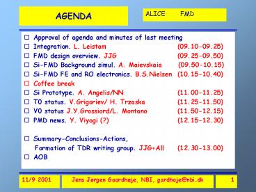
- Approval of agenda and minutes of last meeting
- Integration. L. Leistam (09.10-09.25)
- FMD design overview. JJG (09.25-09.50)
- Si-FMD Background simul. A. Maievskaia
(09.50-10.15) - Si-FMD FE and RO electronics. B.S.Nielsen
(10.15-10.40) - Coffee break
- Si Prototype. A. Angelis/NN (11.00-11.25)
- T0 status. V.Grigoriev/ H. Trzaska
(11.25-11.50) - V0 status J.Y.Grossiord/L. Montano (11.50-12.15)
- PMD news. Y. Viyogi (?) (12.15-12.30)
- Summary-Conclusions-Actions,
- Formation of TDR writing group. JJGAll
(12.30-13.00) - AOB
2
Main issues
- Si-FMD
- Freeze inner radius? Freeze general geometry.
- Integration with ITS and other FD
- Define Services (cables, cooling, etc.)
- Define Responsibilities, timetable
- Go to bids. Commence Prototyping.
- T0
- Define final geometry (L,R)
- Trigger
- Timetable
- Go to prototyping
- V0
- Design status
- Integration, trigger
- Prototyping.
- Organization
- Responsibilities
- TDR writing group formation
3
Overall Geometry
- -5.4lt ? lt-1.6
- 3 lt ? lt 1.6
Si 4
Si3(moved)
Si2
Si1
4
Integration in ALICE
Si-1
V0-R
Si-2
T0-R
Si-3
5
Si1 with 6 Wafers
Si 1 outer
2 Rings
Si 1 inner
6
Si1 with 6 Wafers
Outer Ring
24
R35.1cm
24
16
R22.1cm
R39.9cm
8
R28.8cm
R17.1cm
R5.3cm
2 Rings
Inner Ring
7
Ring geometry
!!30 cm vertex shift ? ?1.2
8
Background and acceptance
- Pseudorapidity coverage
- Si1 Si2 (inner and outer)
- d(IR)62.8 and 75.8 cm
- 1.51 lt?lt 1.94
- 2.03 lt?lt 3.58
- Si3 d(IR)345cm
- -5.28 lt?lt -3.71
- Vertex shift (30cm) d? ? 0.3
9
Background simulationsAlla Maevskaia
10
Background simulationsAlla Maevskaia
11
Background simulationsAlla Maevskaia
12
Background simulationsAlla Maevskaia
13
RHIC vs. LHC
BRAHMS _at_ RHIC 200
- RHIC
- (?s130 AGeV)
- -5 lt?lt 5
- Plateau 2 lt?lt 2
- (40 of range)
- dN/d?(?0)550.
- (?s200 AGeV)
- -6 lt?lt 6 dN/d?(?0)610.
- Nch 5100
- LHC
- (?s5800 AGeV)
- -9 lt?lt 9
BRAHMS 200AGEV
14
Limiting particle prod. in fragmentation region
- RHIC saturation of particle production in
fragmentation region is already achieved at SPS. - ?Width of Frag. Region is
- ?? ? 3.
- LHC ? (9,9)
- RHIC200 ? (6,6).
- ? May expect that central region at LHC extends
to (6,6). - ? Si-FMD and V0 detectors cover (-1.5,5.3), i.e.
interesting region.
BRAHMS RHIC 200. Prelim
BRAHMS. Subm. to Phys Lett. B. 2001
15
Si-FMD Role in Trigger
- Physics and rates
- Central PbPb
- Nch(Si) 15.000-20.000
- pp
- Nch(Si) 50-100
- PbPb 8kHz. (1kHz central)
- Average event spacing gt100?s
- pp up to 1 coll/bunch crossing
- Average event spacing 25 ns
- WHO does it?
- LVL0 Timing T0
- Vertex (? 1-2 cm) T0
- Vertex (? 0.1-0.2 cm) TPC
- Rough on-line Centrality cut on dE
V0 - pp trigger V0
- Timingvertex(pp) T0,V0
- Precise centrality Si
- Fluctuations Si
- Azimuthal distribution Si
- Off-Line PID (dE) Si
- Level 0 T0,V0
- Off-line, Higher level Si
16
Electronics overview
- Assume 128 strips/wafer
- Assume 32 channels/chip
- Assume 8 chips/RO card
17
Cost Estimate
- VERY uncertain and preliminary estimate
- in CHF.
- 6Ø still experimental
- Test production batch 16-25 wafers
18
Si-FMD Timetable
- .
19
Responsibilities Si-FMD
- TASKS
- Update geometry and integration drawings
- Update simulations of background, resolution and
performance - Choice of electronics
- Tender and order prototype 6 wafers
- Construct and test FERO system
- Test DAQ and integrate with DAQ
- Update prelim-TDR-started
- PPR- needs to develop
- WHO?
- NBI
- INR
- NBI
- NBI
- NBI ?
- ?
- NBI, INR, Athens, ?
20
Responsibilities T0 V0
- TASK
- T0 Tech. Design study
- T0- technology decision and funding
- T0 prototyping
- V0 TDR
- Prototyping
- Who?
- MEPHI and Jyvaskyla
- Lyon and Mexico
21
Endorsed Recommendation to ALICE Forum,TB,MB,CB
- Si-FMD acceptance downscoped to
-5.28 lt ? lt -3.71 - 1.51 lt ? lt 3.58
- Background from beam pipe important-gt redesign
needs to be pursued - Si-FMD not present in trigger at LVL0. Analog
sum trigger for LVL1 seems possible but not
likely. - FEE /(ampl. Chip. Hybrid, ADC, receiver) can be
developed together with IDEAS-Norway. - Revisit ? segmentation for flow analysis
- T0 is main Alice timing trigger
- Two arm necessary for good vertex also in absence
of TPC and pixels - Radiator-PM is baseline design
- Two-arm V0 for beam gas-rejection
- V0 is main Alice centrality trigger
- Integrate Si3, T0(L), V0(L) and PMD
Recommended
CrystalGraphics Presentations


