
Standards for loading to Interpretation Projects: - PowerPoint PPT Presentation
1 / 23
Title:
Standards for loading to Interpretation Projects:
Description:
SP-CDP relation in case of 2D and full fold grid for 3D ... From Pitfalls in 3-D Seismic Interpretation' By Alistair R. Brown. Phase and Polarity ... – PowerPoint PPT presentation
Number of Views:262
Avg rating:3.0/5.0
Title: Standards for loading to Interpretation Projects:
1
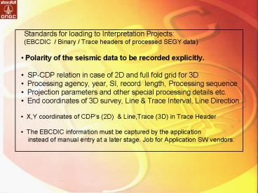
- Standards for loading to Interpretation
Projects - (EBCDIC / Binary / Trace headers of processed
SEGY data) - Polarity of the seismic data to be recorded
explicitly. - SP-CDP relation in case of 2D and full fold
grid for 3D - Processing agency, year, SI, record
length, Processing sequence - Projection parameters and other special
processing details etc. - End coordinates of 3D survey, Line Trace
Interval, Line Direction - X,Y coordinates of CDPs (2D) Line,Trace
(3D) in Trace Header - The EBCDIC information must be captured by the
application - instead of manual entry at a later stage. Job
for Application SW vendors.
2
Phase and Polarity Every seismic interpreter,
has the responsibility to determine or verify the
phase and polarity of his or her data. Data
phase and polarity critically determine seismic
character Character is key in making an
effective well tie and thus correctly identifying
seismic horizons.
Seismic section with dry hole (peak-over-trough)
and good well (trough-over-peak) penetrate high
amplitudes, but only the latter with
red-over-blue is representative of low-impedance
prospective sand. From Pitfalls in 3-D Seismic
Interpretation By Alistair R. Brown
3
- Interpretation related
- Seismic data loading application should also read
X, Y coordinates along with SP/Line CDP/Trace - If X, Y coordinates are different from Seismic
Project, then the application should throw a
warning message. This is to prevent wrong data to
be loaded - Interpreted data must seamlessly be accessible
across various platforms, various third party
applications - Is there any Standard way to exchange
interpretation data?
4
(No Transcript)
5
(No Transcript)
6
(No Transcript)
7
(No Transcript)
8
The SEGY Dilemma For seismic data exchange SEG
Y format is widely used ever since its release in
1975. Individual companies had modified it from
time to time to suit their own needs and to
include the requirements of 3D data. Therefore,
the SEGY rev(1) format released belatedly in 2002
has not been accepted by the industry as they see
little benefit to change from their own
version. In addition, Geophysical community has
difficulty on agreeing on any single standard
because Various companies have used the binary
header to store both ASCII characters and IEEE
floating point numbers contrary to SEGY
standards. This is because Extracting
information from the Extended Textual File is
more complicated than extracting information from
the binary header. The sample value format code
definitions suggested by SEGY rev 1 were already
in use for a different purpose by some companies.
9
Due to conflicting concerns and interests of the
companies and time to time customization of
existing formats to meet their individual needs,
there are too many standards and large data
exists in those customized formats. Added to
this, there are no standards set for exchange of
the derived velocity data and other seismic
attributes and interpretation data.
Therefore ONGC has felt the need to standardize
various seismic related data for seamless data
flow and interoperability, independent of the
application S/W. Broadly they are
Standardization of All the Seismic SEGY
Headers. Naming conventions in API. Line Summary,
Observers reports and all other Acquisition QC
reports Writing of these meta data along with
seismic data. Capturing meta data during
processing and interpretation and
storing. Transfer of seismic related data of over
NETWORK
10
EBCDIC Header Standardization C 1 CLIENT OIL
AND NATURAL GAS CORPORATION LIMITED. 2D SEISMIC
DATA C 2 LINE M125-02
SURVEY xxxxxxxxxxxxxxxx AREAxxxxxxxxxxxxxxxxxx
C 3 SPHEROID EVEREST75 PROJECTIONUTM-44
CM 81 CP2 XX C 4 FSP
74 IS AT LAT 11 12 18.12 N LON 79
30 29.01 E C 5 LSP 1088 IS
AT LAT 11 01 26.84 N LON 79 20 42.52 E
C 6 FCDP 1 SP ON FCDP 1
LCDP 1088 SP ON LCDP 1088 C 7 ADDITIONAL
SP CDP RELATION PAIRS FOR CROOKED PROFILE
(OTHERWISE BLANK) C 8 ADDITIONAL SP CDP
RELATION PAIRS FOR CROOKED PROFILE (OTHERWISE
BLANK) C 9 BLANK
C10
ACQUISITION PARAMETERS
C11 RECORDING YEAR
2004 AGENCYONGC
VESSEL/PARTYGP-29 C12 SYSTEMDFS-IV
REC FORMATSEG-B
LOW/HIGHCUT 8/128 HZ C13 NO OF
CHANNELS 96 FOLD 48
SOURCE VIBROSEIS C14 SAMPLE
INTERVAL 2MS REC LENGTH 5000 MS REC
START TIME 0MS C15 SHOT INTERVAL 100 M
GROUP INTERVAL 100 M NEAR OFFSET 200 M
C16 LAYOUTSPLITSPREAD BACK CHANNELS 72
FORWARD CHANNELS 24 C17 ENTER
ADDITIONAL INFORMATION HERE
C18 ENTER ADDITIONAL
INFORMATION HERE
C19 BLANK
C20
PROCESSING PARAMETERS AGENCY RCC, CHENNAI, ONGC
BASIC/REPROCESSING C21 to C34 PROCESSING
STEPS C35 BLANK
C36 PROCESSED OUTPUT STORED
IN THIS TAPEDMOSTK/MISTK/PSTM/PSDM
C37 DOMAINTIME/DEPTH REC LENGTH 4000
MS SAMPLE INTERVAL 4 MS C38 ADDITIONAL
INFORMATION C39 BLANK
C40
END EBCDIC
11
MANDATORY LOCATIONS TO BE UPDATED IN BINARY
HEADER 17 - 18 SAMPLE INTERVAL IN MICRO
SECONDS. 21 - 22 NUMBER OF SAMPLES PER DATA
TRACE. 25 - 26 DATA SAMPLE FORMAT CODE. 27
- 28 EXPECTED NUMBER OF TRACES PER ENSEMBLE.
SHOULD BE 1 FOR POST STACK DATA. 29 - 30
TRACE SORTING CODE. SHOULD BE 4 FOR STACK DATA
55 - 56 MEASUREMENT SYSTEM. 1 FOR METERS 2-
FEET (RECOMMENDED TO UPDATE THIS FIELD) 301 - 302
SEGY FORMAT REVISION NUMBER SHOULD BE 0 303
- 304 FIXED TRACE LENGTH FLAG. SHOULD BE 0
305 - 306 EXTENDED TEXTUAL FILE HEADER
RECORDS AFTER BINARY HEADER. SHOULD BE 0
12
MANDATORY LOCATIONS IN TRACE HEADER 1 - 4
TRACE SEQUENCE NUMBER WITHIN THE LINE 21 -
24 CDP NUMBER 29 - 30 TRACE
IDENTIFICATION CODE. SHOULD BE 1 FOR SEISMIC
DATA 71 - 72 SCALAR TO BE APPLIED TO
COORDINATES IN 181-188 TO GIVE THE REAL VALUE.
POSSIBLE VALUES ARE 1, 10, 100,
1000 OR 10000. IF VE, SCALAR IS USED AS
MULTIPLIER IF -VE, SCALAR IS
USED AS DIVISIOR. SHOULD BE 1 IF X,Y ARE GIVEN IN
METERS. 115 - 116 NUMBER OF SAMPLES IN THIS
TRACE 117 - 118 SAMPLE INTERVAL IN MICRO SECONDS
FOR THIS TRACE. 181 - 184 X COORDINATE OF THIS
TRACE I85 - 188 Y COORDINATE OF THIS TRACE 197
- 200 SHOTPOINT NUMBER FOR THIS TRACE 201 - 202
SCALAR TO BE APPLIED TO THE SHOT POINT NUMBER IN
197-200. IF 0, THE SHOT POINT IS
TAKEN AS SUCH. IF VE, SCALAR IS
USED AS MULTIPLIER IF -VE, SCALAR IS USED AS
DIVISIOR. EXAMPLE IF SHOT POINT
ABOVE CDP 101 IS 50.5, IT SHOULD BE STORED AS
505 IN LOCATIONS 197-200
AND -10 AS SCALAR IN LOCATION 201-202
13
The above example is another variation of SEGY,
i.e. ONGC SEGY. However, it gives us an idea
that what is the minimum expected in the SEGY
format that can be agreed upon to load data
without any errors. In doing so, may be we are
focusing on the wrong item. Instead of
insisting on the universally standard segy
format, we should be focused on how to describe
our customized SEGY format i.e. Flexible data
format standards Here comes XML What is
XML? XML was designed to describe data and to
focus on what data is. i.e. Self defining data
formats (with structural definitions and data
contents) XML is a cross-platform, software and
hardware independent tool for transmitting
information in systematically accurate and
consistent way. With XML, data can be exchanged
between incompatible systems
14
Here is a part of XML file describing the segy
headers lt?xml version"1.0" encoding"ISO-8859-1"
?gt - ltsegy EBCDIC"3200" Binary"400"
Trace"240" Sample_Format"IBMFP"gt lttitlegtONGC
SEGY STANDARDlt/titlegt ltcommentgtStandards for
storing seismic data in SeisDBlt/commentgt
ltdategtImplemented March 2005lt/dategt
ltheaderstring Header"EBCDIC" Byte"91" Size"16"
Type"EBCDIC"gtLine_Namelt/headerstringgt
ltheaderstring Header"EBCDIC" Byte"116"
Size20" Type"EBCDIC"gtSurvey_Namelt/headerstringgt
ltheaderstring Header"EBCDIC" Byte"174"
Size"14" Type"EBCDIC"gtSpheroid_Namelt/headerstrin
ggt ltheaderstring Header"EBCDIC" Byte"250"
Size"6" Type"EBCDIC"gtFirst_Shot_Pointlt/headerstr
inggt ......... ltheaderword
Header"Binary" Byte"17" Type"16BitInteger"
Scale"-1000"gtSample_Intervallt/headerwordgt
ltheaderword Header"Binary" Byte"21"
Type"16BitInteger" Scale"1"gtSamples_Per_Tracelt/h
eaderwordgt ltheaderword Header"Binary"
Byte"25" Type"16BitInteger" Scale"1"gtSample_For
mat_Codelt/headerwordgt .........
ltheaderword Header"Trace" Byte"1"
Type"32BitInteger" Scale"1"gtTrace_Sequence_Numbe
rlt/headerwordgt ltheaderword Header"Trace"
Byte"17" Type"32BitInteger" Scale"1"gtShot_Seque
nce_Numberlt/headerwordgt ltheaderword
Header"Trace" Byte"21" Type"32BitInteger"
Scale"1"gtCDP_Numberlt/headerwordgt .........
ltheaderword Header"Trace" Byte"181"
Type"IEEEFP" Scale"1"gtCdp_Xlt/headerwordgt
ltheaderword Header"Trace" Byte"185"
Type"IEEEFP" Scale"1"gtCdp_Ylt/headerwordgt
lt/segygt
15
You may notice that with this type of
description, what needs to be agreed upon is the
naming convention for various headers and the
maximum size and not the location or the way the
values are stored. Look at the deviation of the
way the Cdp_X is stored as IEEE floating point by
some companies that can easily be
handled. ltheaderword Header"Trace" Byte"181"
Type"IEEEFP" scale"1"gtCdp_Xlt/headerwordgt
Local naming conventions can be followed within
the definition in XML. For example Survey_Name
will be of max 20 characters. It can be sub
divided as per the local standards as 1) Basin
Code Four Characters For Onshore-Two
Characters i.e. ON 2) Separator-One Character
Block Code-Three characters 3) 2D or 3D-Two
characters Separator-One Character 4) State
Code-Max two Characters Investigation No-Max
five characters Examples CMBYON-ANK3D-G423 ,
CMBYON-ANK3D-MERGE1
16
Interpretation related
To avoid significant loss of time and knowledge
invested in prior studies Seismic
Interpretation software should automatically
capture all the metadata associated with seismic
data, interpreted horizons, faults, seismic
attributes, grids, maps, etc. This is necessary
to capture, store and effectively manage
interpretation results, data and knowledge went
into the interpretation of geo-scientific
data This is applicable to all the
geo-scientific data (Well Logs)
17
Meta data Within the application, the data is
known. But while exchanging seismic data,
information like vertical axis (time, depth,
frequency), attribute stored (amplitude,
impedance, velocity ...) and the unit ...... do
not automatically go to the exported
data. Similarly, for time Horizons, the
associated geologic surface etc do not go to the
exported data automatically.
18
Many Players in the same area.
- Archiving and exchanging Media
- Platform independent archives
- It is not possible to have all kinds or tape
drives with every one. - Which media is suitable for long time archival ?
- 3590, 3592, DLT, SDLT(160,320), LTO (1,2,3)
- Various types of media and drives results in
significant loss of time while transferring the
seismic data. - Appropriate loss less compression method to
send/receive the data over the network
19
We can also standardize Seismic compression and
transmission of data over the network using
XML Seismic data huge datasets, large dynamic
range, complex geometric features, highly
oscillatory and suitable for Wavelet
compression. For post-stack data, the data
compressions of the order of 50 can easily be
achieved without much loss that can be used for
interpretation.
Different sub-bands contain different seismic
information. It is crucial to choose different
quantization procedures for each sub-band. For
example, the low-frequency and low-wave number
sub-band contains most of the seismic reflection
energy.
20
Compression ratio 50
Difference is essentially noise
21
Uniformity is Thy Name Documentation of Best
Practices is the need Then only Valuable time and
resources that are spent on data manipulation
tasks can be utilized to analysis and decision
making tasks.
22
The Road Ahead
- Collaboration among the
- EP Players, Equipment Manufacturers, API
Operators and - Common acceptable standard practices to ensure
- Interoperability
- Reduced cycle times
- Correctness of interpreted results.
23
Thank You for Your Time
24
(No Transcript)
Recommended
CrystalGraphics Presentations


