
Technisonic Industries TDFM136 PowerPoint PPT Presentation
1 / 21
Title: Technisonic Industries TDFM136
1
Technisonic IndustriesTDFM-136
2
TDFM-136 Transceiver Operation
3
TDFM-136 Transceiver Operation - Overview
- Radio Familiarization
- Front Panel Layout and Controls
- Basic Operation
- Channel and Memory Select
- Programming the Radio
- Command Architecture
- Operating Commands
- Channel Data Commands
- Configuration Commands
- PC Software Use (TDP-136)?
- Connections
- Operation
4
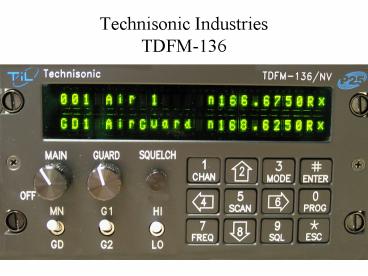
Radio Familiarization - Front Panel Layout and
Controls
1. Squelch Indicators (LED) Lights when signal
is received. 2. Channel Display (2Line x 24
character) Shows channel parameters. 3. MAIN
(RotarySwitch) Power ON/OFF and Main channel
volume control. 4. GUARD (Rotary) Guard channel
volume control. 5. Squelch Defeat (Push button)
Press to open squelch (in analog modes of
operation)? 6. MN/GD (Toggle Switch) Selects
active channel (Main or Guard) for transmit and
edit functions. 7. G1/G2 (Toggle Switch)
Selects active Guard memory G1 or G2 for transmit
and edit functions. 8. HI/LO (Toggle Switch)
Selects Transmit Power High (10w) or Low
(1w). 9. Keypad (12 Keys) Control radio
functions, 3 command levels.
5
Radio Familiarization Channel Display
1. Main channel information is displayed on the
top row of the display. 2. Guard channel
information is displayed on the bottom row of the
display. 3. The Main channel can have up to 230
memory positions (001 to 230), the current active
memory number for the Main channel is shown
in the first three characters of the line. 4. The
Guard channel can have two memories, GD1 and GD2,
the currently active Guard memory number is
shown in the first three lines of the bottom
row. 5. Memories for the Main channel can be
scanned, when in use scan information is shown at
the 4th character position on the top
row. 6. The current command level is indicated on
the bottom row at the 4th character position.
6
Radio Familiarization Channel Display
The following parameters are common to both the
Main and the Guard channels. 7. Up to eight
characters are available for a text description
of the memory. 8. One character position is
used to indicate the operating mode
Analog modes wide "w"(25kHz.), narrow "n"
(12.5kHz.)? Digital mode project 25
digital "D" (12.5kHz.). 9. Eight characters are
used to indicate the frequency in use. 10. One
character indicates either Receive or Transmit
as "R" or "T". 11. The final character indicates
the current squelch mode Analog modes
noise squelch "x", CTCSS tones "t", DCS codes
"c" Digital modes monitor "m", NAC only
"n", and TalkGroup NAC "g"
7
Radio Familiarization Basic Operation
The basic operation for transmit and receive is
as follows 1. The Squelch LED's are on if a
valid signal has been received. 2. Upon keying
the radio, the "R" character at the second from
right position on the line, will change to
a "T". The character will revert to a "R" upon
releasing PTT. 3. The "MAIN" and "GUARD
receive audio volumes are separately
controlled. 4. In analog modes the "SQUELCH"
pushbutton opens the squelch, in digital it opens
upon receiving any valid digital signal. 5.
The transmit power level can be set to 1W (low)
or 10W (high).
8
Radio Familiarization Select Channel and Memory
1. The MAIN channel data is shown on the top
line of the display, MAIN supports 230 memory
positions (001 to 230). MAIN is selected
for edit and transmit by placing the MN/GD switch
in the MN position. 2. When the MAIN channel
is selected, a specific memory may be selected by
pressing the "CHAN" key and then directly
entering the memory number (001-230), or by using
the forward or backward arrow keys (6 4)
to scroll through the programmed memories. 3.
The GUARD channel has two memories GD1 and GD2.
When the MN/GD switch is in the GD position
then the GUARD memory used is determined by the
position of the G1/G2 switch.
9
Programming the Radio Command Architecture
10
Programming the Radio Command Architecture
Command Scope The commands can be characterized
as belonging in one of three categories Operatin
g commands are those which perform a direct
function related to the use of the radio. Edit
comands allow the user to Edit the RF channel
parameters (frequency, mode etc). Configuration
comands affect how the radio operates, including
how other commands work.
Command Nomenclature The commands and command
levels are abbreviated as follows Command
Levels are abbreviated as Ln, where 'n' is the
level number from 1 to 5. example L2 command
level 2 Command Numbers are
abbreviated as -n, where 'n' is the command
number from 0 to 9. example L2-1 command
level 2, command 1 (Edit all/new channel)?
Command Description The commands are described
in detail in both the Technisonic
documents TDFM-136 Operators Manual, (TiL
document 99RE266) and the TDFM-136 Installation
and Operating Instructions, (TiL document
99RE255)? These documents are available on-line
at www.til.ca.
11
Programming the Radio Operating Commands
Operating Command List The Operating Commands
are distributed across Level 1, Level 2 and Level
3 as follows Level 1 L1-1 jump to selected
channel L1-2 and L1-8 change display
brightness L1-4 and L1-6 scroll through
programmed memories on MAIN channel L1-5
start/stop scan Level 2 L2-2 copy current GUARD
channel data to current MAIN channel. L2-3 lock
keypad L2-8 copy current MAIN channel data to
current GUARD channel. Level 3 L2-9 display
current Squelch Parameters.
12
Programming the Radio Edit Commands
Edit Commands - Cursor and Prompts When any Edit
begins, a cursor is placed in the appropriate
data field on the display, and the
non-active channel becomes a prompt
line. Example for 'Edit Frequency' on the MAIN
Channel, a cursor is placed at the second
character in the Frequency field (1), and the
Guard display row becomes a prompt line (2).
When editing the Guard frequency, the situation
is reversed, the cursor is placed on the GUARD
row (1), and the MAIN row becomes the prompt line.
13
Programming Channel Data Edit Commands
Edit Command List The Edit Commands are
distributed across Level 1 and Level 2 as
follows Level 1 L1-3 Edit current Operating
Mode (analog wide, analog narrow, P25
digital). L1-7 Edit current Frequency (136.0000
to 174.0000 MHz.)? L1-9 Edit current Squelcy
mode (analog or digital depending on current
Operating Mode)? Level 2 L2-1 Edit all current
channel or Create New Memory (MAIN only). L2-5
Edit Scan list (MAIN only). L2-6 Edit current
Text Description. L2-7 Create Shadow Channel
(MAIN only). L2-8 Edit Unit ID.
14
Programming Channel Data Configuration Commands
Configuration Command List The Configuration
Commands are Level 3 and Level 4 as
follows Level 3 L3-1 Set Boot Memory for MAIN
(Last Selected, Last Programmed). L3-3 Set HEX /
Decimal Edit for TalkGroup NAC. L3-4 Show
current firmware version. L3-5 Set Scan
Parameters (revert mode, reply timer, monitor
timer, delay timer). L3-6 Set PTT Max Timer (30,
60, 90 seconds). L3-7 Set Sidetone Audio L3-8
Communicate with PC (for PC programming).
15
Programming Channel Data Configuration Commands
Configuration Command List continued Level 4
(Maintenance Level protected access)? L4-1
Set channel defaults for Edit all. L4-2 Memory
test. L4-3 Restrict Operator Level
Commands. L4-4 Channel Scroll test (MAIN
only). L4-7 Re-build RF Database (tries to
rebuild corrupted database in RF modules). L4-8
Erase All Memories and Re-boot (Set to as shipped
from factory). L4-9 Restrict Squelch Options.
16
PC Software TDP-136
Setup 1. PC with serial port, or USB-Serial
converter Operation Note that the TDP-136
manual is available on-line at www.til.ca. 1. Fol
low Manual Instructions, available
on-line. Note the TDFM-136 does NOT
work with MultiTDP, you must use TDP-136.
17
?? Questions ??
18
TDFM-136 Operators Guide
See www.fs.fed.us/fire/niicd/documents.html
19
TDFM-136 PC Cable
20
NIICD TDFM-136 Cheat Sheet
See www.fs.fed.us/fire/niicd/documents.html
21
NIICD TDFM-136 Configuration Settings
See www.fs.fed.us/fire/niicd/niicd_contacts.html
for Avionics contact information
Recommended
