
Synthesis vs. Compilation - PowerPoint PPT Presentation
1 / 26
Title:
Synthesis vs. Compilation
Description:
Verilog and VHDL started out as simulation languages, but soon programs were ... force, release, and hierarchical net names (for simulation only) ... – PowerPoint PPT presentation
Number of Views:124
Avg rating:3.0/5.0
Title: Synthesis vs. Compilation
1
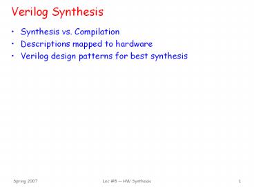
Verilog Synthesis
- Synthesis vs. Compilation
- Descriptions mapped to hardware
- Verilog design patterns for best synthesis
2
Logic Synthesis
- Verilog and VHDL started out as simulation
languages, but soon programs were written to
automatically convert Verilog code into low-level
circuit descriptions (netlists). - Synthesis converts Verilog (or other HDL)
descriptions to an implementation using
technology-specific primitives - For FPGAs LUTs, flip-flops, and RAM blocks
- For ASICs standard cell gate and flip-flop
libraries, and memory blocks
3
Why Perform Logic Synthesis?
- Automatically manages many details of the design
process - Fewer bugs
- Improves productivity
- Abstracts the design data (HDL description) from
any particular implementation technology - Designs can be re-synthesized targeting different
chip technologies E.g. first implement in
FPGA then later in ASIC - In some cases, leads to a more optimal design
than could be achieved by manual means (e.g.
logic optimization)
Why Not Logic Synthesis?
- May lead to less than optimal designs in some
cases
4
How Does It Work?
- Variety of general and ad-hoc (special case)
methods - Instantiation maintains a library of primitive
modules (AND, OR, etc.) and user defined modules - Macro expansion/substitution a large set of
language operators (, -, Boolean operators,
etc.) and constructs (if-else, case) expand into
special circuits - Inference special patterns are detected in the
language description and treated specially
(e.g., inferring memory blocks from variable
declaration and read/write statements, FSM
detection and generation from always _at_ (posedge
clk) blocks) - Logic optimization Boolean operations are
grouped and optimized with logic minimization
techniques - Structural reorganization advanced techniques
including sharing of operators, and retiming of
circuits (moving FFs), and others
5
Operators
- Logical operators map into primitive logic gates
- Arithmetic operators map into adders,
subtractors, - Unsigned 2s complement
- Model carry target is one-bit wider that source
- Watch out for , , and /
- Relational operators generate comparators
- Shifts by constant amount are just wire
connections - No logic involved
- Variable shift amounts a whole different story
--- shifter - Conditional expression generates logic or MUX
Y X ltlt 2
X3
Y5
X2
Y4
X1
Y3
X0
Y2
Y1
Y0
6
Synthesis vs. Compilation
- Compiler
- Recognizes all possible constructs in a formally
defined program language - Translates them to a machine language
representation of execution process - Synthesis
- Recognizes a target dependent subset of a
hardware description language - Maps to collection of concrete hardware resources
- Iterative tool in the design flow
7
Simple Example
- module foo (a,b,s0,s1,f)
- input 30 a
- input 30 b
- input s0,s1
- output 30 f
- reg f
- always _at_ (a or b or s0 or s1)
- if (!s0 s1 s0) fa else fb
- endmodule
- Should expand if-else into 4-bit wide multiplexer
(a, b, f are 4-bit vectors) and optimize/minimize
the control logic
8
Module Template
Synthesis tools expects to find modules in this
format.
- module lttop_module_namegt(ltport listgt)
- / Port declarations. followed by wire, reg,
integer, task and function declarations / - / Describe hardware with one or more continuous
assignments, always blocks, module
instantiations and gate instantiations / - // Continuous assignment
- wire ltresult_signal_namegt
- assign ltresult_signal_namegt ltexpressiongt
- // always block
- always _at_(ltevent expressiongt)
- begin
- // Procedural assignments
- // if statements
- // case, casex, and casez statements
- // while, repeat and for loops
- // user task and user function calls
- end
- // Module instantiation
- ltmodule_namegt ltinstance_namegt (ltport listgt)
- // Instantiation of built-in gate primitive
- gate_type_keyword (ltport listgt)
- Order of these statements is irrelevant, all
execute concurrently - Statements between the begin and end in an always
block execute sequentially from top to bottom
(however, beware of blocking versus non-blocking
assignment) - Statements within a fork-join statement in an
always block execute concurrently
9
Procedural Assignments
- Verilog has two types of assignments within
always blocks - Blocking procedural assignment
- RHS is executed and assignment is completed
before the next statement is executed e.g., - Assume A holds the value 1 A2 BA A is
left with 2, B with 2. - Non-blocking procedural assignment lt
- RHS is executed and assignment takes place at the
end of the current time step (not clock cycle)
e.g., - Assume A holds the value 1 Alt2 BltA A is
left with 2, B with 1. - Notion of current time step is tricky in
synthesis, so to guarantee that your simulation
matches the behavior of the synthesized circuit,
follow these rules - Use blocking assignments to model combinational
logic within an always block - Use non-blocking assignments to implement
sequential logic - Do not mix blocking and non-blocking assignments
in the same always block - Do not make assignments to the same variable from
more than one always block
10
Supported Verilog Constructs
- Net types wire, tri, supply1, supply0 register
types reg, integer, time (64 bit reg) arrays of
reg - Continuous assignments
- Gate primitive and module instantiations
- always blocks, user tasks, user functions
- inputs, outputs, and inouts to a module
- All operators (, -, , /, , lt, gt, lt, gt, ,
!, , !, , , !, , , , , , , ,
, ltlt, gtgt, ?, , ) Note / and are
supported for compile-time constants and constant
powers of 2 - Procedural statements if-else-if, case, casex,
casez, for, repeat, while, forever, begin, end,
fork, join
- Procedural assignments blocking assignments ,
nonblocking assignments lt (Note lt cannot be
mixed with for the same register). - Compiler directives define, ifdef, else,
endif, include, undef - Miscellaneous
- Integer ranges and parameter ranges
- Local declarations to begin-end block
- Variable indexing of bit vectors on the left and
right sides of assignments
11
Unsupported Language Constructs
Generate error and halt synthesis
Simply ignored
- Net types trireg, wor, trior, wand, triand,
tri0, tri1, and charge strength - register type real
- Built-in unidirectional and bidirectional
switches, and pull-up, pull-down - Procedural statements assign (different from the
continuous assignment), deassign, wait - Named events and event triggers
- UDPs (user defined primitives) and specify blocks
- force, release, and hierarchical net names (for
simulation only)
- Delay, delay control, and drive strength
- Scalared, vectored
- Initial block
- Compiler directives (except for define, ifdef,
else, endif, include, and undef, which are
supported) - Calls to system tasks and system functions (they
are only for simulation)
12
Combinational Logic
- CL can be generated using
- Primitive gate instantiation
- AND, OR, etc.
- Continuous assignment (assign keyword), example
- Module adder_8 (cout, sum, a, b, cin)
- output cout
- output 70 sum
- input cin
- input 70 a, b
- assign cout, sum a b cin
- endmodule
- Always block
- always _at_ (event_expression)
- begin
- // procedural assignment statements, if
statements, - // case statements, while, repeat, and for
loops. - // Task and function calls
13
Combinational Logic Always Blocks
- Make sure all signals assigned in a combinational
always block are explicitly assigned values every
time that the always block executes--otherwise
latches will be generated to hold the last value
for the signals not assigned values!
module mux4to1 (out, a, b, c, d, sel) output
out input a, b, c, d input 10 sel reg
out always _at_(sel or a or b or c or d) begin
case (sel) 2'd0 out a 2'd1 out b
2'd3 out d endcase end endmodule
- Example
- Sel case value 2d2 omitted
- Out is not updated when select line has 2d2
- Latch is added by tool to hold the last value of
out under this condition
14
Combinational Logic Always Blocks (cont.)
- To avoid synthesizing a latch in this case, add
the missing select line - 2'd2 out c
- Or, in general, use the default case
- default out foo
- If you dont care about the assignment in a case
(for instance you know that it will never come
up) then assign the value x to the variable
E.g. - default out 1bx
- The x is treated as a dont care for synthesis
and will simplify the logic - (The synthesis directive full_case will
accomplish the same, but can lead to differences
between simulation and synthesis.)
15
Latch Rule
- If a variable is not assigned in all possible
executions of an always statement then a latch is
inferred - E.g., when not assigned in all branches of an if
or case - Even a variable declared locally within an always
is inferred as a latch if incompletely assigned
in a conditional statement
16
Encoder Example
- Nested IF-ELSE might lead to priority logic
- Example 4-to-2 encoder
- This style of cascaded logic may adversely affect
the performance of the circuit
always _at_(x) begin encode if (x 4'b0001) y
2'b00 else if (x 4'b0010) y 2'b01 else
if (x 4'b0100) y 2'b10 else if (x
4'b1000) y 2'b11 else y 2'bxx end
17
Encoder Example (cont.)
- To avoid priority logic use the case construct
- All cases are matched in parallel
- Note, you dont need the parallel case
directive (except under special circumstances,
described later)
always _at_(x) begin encode case (x) 4b0001 y
2'b00 4b0010 y 2'b01 4'b0100 y
2'b10 4'b1000 y 2'b11 default y 2'bxx
endcase end
18
Encoder Example (cont.)
- Circuit would be simplified during synthesis to
take advantage of constant values as follows and
other Boolean equalities
A similar simplification would be applied to the
if-else version also
19
Encoder Example (cont.)
- If you can guarantee that only one 1 appears in
the input (one hot encoding), then simpler logic
can be generated - If the input applied has more than one 1, then
this version functions as a priority encoder --
least significant 1 gets priority (the more
significant 1s are ignored) the circuit will be
simplified when possible
always _at_(x) begin encode if (x0) y 2'b00
else if (x1) y 2'b01 else if (x2) y
2'b10 else if (x3) y 2'b11 else y
2'bxx end
20
Encoder Example (cont.)
- Parallel version, assuming we can guarantee only
one 1 in the input - Note now more than one case might match the input
- Therefore use parallel case directive without
it, synthesis adds appropriate matching logic to
force priority - Semantics of case construct says that the cases
are evaluated from top to bottom - Only an issue for synthesis when more than one
case could match input
always _at_(x) begin encode casex (x) //
synthesis parallel_case 4bxxx1 y 2'b00
4bxx1x y 2'b01 4'bx1xx y 2'b10
4'b1xxx y 2'b11 default y 2'bxx
endcase end
21
Encoder Example (cont.)
- Parallel version of priority encoder
- Note parallel case directive is not used,
synthesis adds appropriate matching logic to
force priority - Just what we want for a priority encoder
- Behavior matches that of the if-else version
presented earlier
always _at_(x) begin encode casex (x) 4bxxx1 y
2'b00 4bxx1x y 2'b01 4'bx1xx y
2'b10 4'b1xxx y 2'b11 default y 2'bxx
endcase end
22
Sequential Logic
- Example D flip-flop with synchronous set/reset
- _at_ (posedge clk) key to flip-flop generation
- Note in this case, priority logic is appropriate
- For Xilinx Virtex FPGAs, the tool infers a native
flip-flop - No extra logic needed for set/reset
module dff(q, d, clk, set, rst) input d, clk,
set, rst output q reg q always _at_(posedge
clk) if (reset) q lt 0 else if (set) q lt
1 else q lt d endmodule
We prefer synchronous set/reset, but how would
you specify asynchronous preset/clear?
23
Finite State Machines
module FSM1(clk,rst, enable, data_in,
data_out) input clk, rst, enable input
data_in output data_out / Defined state
encoding this style preferred over defines
/ parameter default2'bxx parameter
idle2'b00 parameter read2'b01 parameter
write2'b10 reg data_out reg 10 state,
next_state / always block for sequential logic
/ always _at_(posedge clk) if (rst) state lt
idle else state lt next_state
- Style guidelines (some of these are to get the
right result, and some just for readability) - Must have reset
- Use separate always blocks for sequential and
combination logic parts - Represent states with defined labels or
enumerated types
24
FSMs (cont.)
/ always block for CL / always _at_(state or
enable or data_in) begin case (state) / For
each state def output and next / idle begin
data_out 1b0 if (enable)
next_state read else
next_state idle end read begin
end write begin end default begin
next_state default data_out 1bx
end endcase end endmodule
- Use CASE statement in an always to implement next
state and output logic - Always use default case and assert the state
variable and output to bx - Avoids implied latches
- Allows use of dont cares leading to simplified
logic - FSM compiler within synthesis tool can
re-encode your states Process is controlled by
using a synthesis attribute (passed in a
comment). - Details in Synplify guide
25
More Help
- Online documentation for Synplify Synthesis Tool
- Under Documents/General Documentation, see
Synplify Web Site/Literaturehttp//www.synplicit
y.com/literature/index.html - Online examples from Synplicity
- Bhasker is a good synthesis reference
- Trial and error with the synthesis tool
- Synplify will display the output of synthesis in
schematic form for your inspection--try different
input and see what it produces
26
Bottom-line
- Have the hardware design clear in your mind when
you write the verilog - Write the verilog to describe that HW
- It is a Hardware Description Language not a
Hardware Imagination Language - If you are very clear, the synthesis tools are
likely to figure it out
Recommended
CrystalGraphics Presentations


