
Simulating a Verilog Description - PowerPoint PPT Presentation
Title:
Simulating a Verilog Description
Description:
I assume that it is all in one directory. Compile and simulate the top file, testbench.v ... Apply test data to all inputs. Add a delay, then check results and ... – PowerPoint PPT presentation
Number of Views:47
Avg rating:3.0/5.0
Title: Simulating a Verilog Description
1
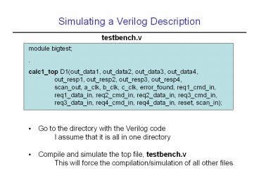
Simulating a Verilog Description
testbench.v
module bigtest . calc1_top D1(out_data1,
out_data2, out_data3, out_data4, out_resp1,
out_resp2, out_resp3, out_resp4, scan_out,
a_clk, b_clk, c_clk, error_found, req1_cmd_in,
req1_data_in, req2_cmd_in, req2_data_in,
req3_cmd_in, req3_data_in, req4_cmd_in,
req4_data_in, reset, scan_in)
- Go to the directory with the Verilog code
- I assume that it is all in one directory
- Compile and simulate the top file, testbench.v
- This will force the compilation/simulation of
all other files
2
Running VCS
- Type vcs -RI testbench.v
- The Interactive Window appears
- All other windows invoked from here
- Window pulldown on top bar
- window icons below top bar
3
Waveform Window
- Open the Waveform Window
- Need to select the signals you want to see, use
Hierarchy Window
4
Hierarchy Window
- Select the bigtest module to see its signals
- Drag-and-drop the signals into the Waveform Window
5
Waveform Window with Signals
- The signals are on display, but they are blank
6
Execute Simulation
- Simulate by selecting Continue
- Printed results are shown in top pane
7
Waveforms Results
- Waveform Window is updated with results
- Zoom out and scroll over time
8
Waveforms Results, Zoomed and Scrolled
9
Testbench for Combinational Logic
initial begin in1 8b00000000 in2
8b0000001l 10 in1 8b00000011 in2
8b00000000 end endmodule
module stimulus reg clk reg 70
in1,in2 wire70 out // instantiate the
design block adder r1(out, in1, in2)
- Apply test data to all inputs
- Add a delay, then check results and apply new
inputs
10
Testbench for Sequential Logic
module stimulus reg clk reg reset wire30
q // instantiate the design block ripple_carry_c
ounter r1(q, clk, reset) // Control the
clock initial clk 1'b0 always 5 clk clk
// Control the reset initial begin reset
1'b1 10 reset 1'b0 20 reset 1'b1 10
reset 1'b0 20 stop end endmodule
- Change inputs before positive clock edge
- Check results after positive clock edge
Recommended
CrystalGraphics Presentations


