
Hydrostatic System PowerPoint PPT Presentation
1 / 15
Title: Hydrostatic System
1
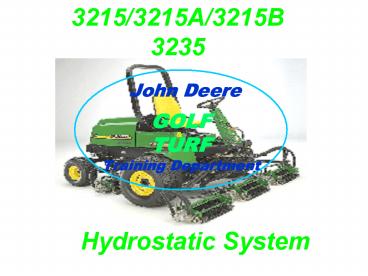
3215/3215A/3215B 3235
Hydrostatic System
2
LWFM Slide Index
(Left Click Selection Box)
Charge Pump
Hydro-Relief Valve
Hydrostatic Pump
Rear Wheel Assist Build
Wheel Motors
Rear Wheel Assist Valves
Hydro-Build the System
Rear Wheel Assist-Off
Hydro-Normal Operation
Rear Wheel Assist-On
Hydro-Dynamic Brake
Reverse/Freewheel Operation
Hydro-Dump Valve
3
Objectives
- Using a Hydraulic Schematic, Trace the Oil Flow
Through Our Hydro Transmission - Describe the Role of the Charge Pump and
Significance of Charge Pressure - Describe 2 Differences Between the Servo Hydro
and the Non-Servo Hydrostatic Transmission
4
Hydrostatic Transmission
- Lets apply what weve learned about JIC symbols
to build the lightweight fairway mower power
train.
5
The charge pump provides several functions to the
hydrostatic circuits Provides flow to keep
circuits primed and makeup internal
leakages. Provides flow, under pressure, for
maintaining back pressure on pump/motors
pistons. Provides flow, under pressure, for
hydraulic control purposes. Provides cooled and
cleansed fluid for temperature control and
flushing. Fluid from the charge pump is directed
through the two dual purpose system relief and
check valve located in the pump backplate. The
charge pump/check valve combination introduces
fluid to both sides of the hydrostatic circuits
and fills or primes all lines, valves, etc.
between the pump and the motor. When the circuit
is primed, the charge pump flow dumps across the
charge pump relief valve to the pump housing to
aid in cooling and flushing the pump. The fluid
then returns to the reservoir. The charge pump
relief valve maintains a minimum charge pressure
level 190 to 220 PSI (13.1 to 15.2 bar ). The
charge pump is capable of producing 4.25 GPM.
6
Charge/ Lift/ Steering Pump
- Functions
- Hydraulic Steering Lift
- Makeup for Internal Leakage
- Keeps Back Pressure on Pump Pistons
- Pumps Oil Through Filter
3215/3215A/3215B/ 3235 NON SERVO
7
1. Bring in the Pumps and Motors that have
already been discussed. 2. Connect the Hydro Pump
to the Motors 3. Students should now recognize
that this is the same type system as that
explained in hydraulic fundamentals. 4. Point out
the Charge Pressure Relief Valve Inlet
Checks High Pressure Reliefs Dump or
TOW valve
8
LWFM Hydrostatic System
- Build the System
3215/3215A/3215B/3235 NON SERVO
9
The hydrostatic pumps provide hydraulic fluid to
the motors though hydraulic lines and fittings.
The hydraulic fluid in the power train circulates
in a closed loop. Fluid leaves the pump and flows
through the motor and is returned to the pump,
not the reservoir. Fluid that leaves this closed
loop circuit, such as case drain, is replenished
by fluid from the charge pump located on the end
of the triple pump assembly.
10
LWFM Hydrostatic System
- NormalOperation
3215/3215A/3215B/3235 NON SERVO
11
Notice that the motors want to act like pumps,
because forces (whether gravity or something
pushing the machine) attempt to make the drive
wheel rotate. The hydro pump is NOT rotating,
thus it is NOT providing oil and blocks the oil
path to the other side of the motors. There is
NO WHERE for the oil to go, thus the drive wheels
are locked. NOTE 1. There will be some
leakage past the hydro pump and motors allowing
the wheels to rotate slightly. 2. Plus, it is
possible for a piston in the hydro axial pump to
be in a position so that it will leak oil
through a lubrication orifice allowing oil to
escape back to sump which results in the wheels
turning. Moral of the Story Hydros provide
dynamic braking, they are NOT designed as a
parking brake. Always set the park brake when
exiting a machine equipped with a hydrostatic
transmission to be sure that it wont run-away.
12
LWFM Hydrostatic System
Motors Want to Act Like Pumps
- Dynamic Brake
3215/3215A/3215B/3235 NON SERVO
13
The purpose of the dump (or TOW) valve is to
allow the movement of a disabled vehicle or if
you want to just push it a short distance,
without starting the engine. If an attempt is
made to push the vehicle the hydrostatic motor
becomes a pump, trying to pump oil through the
system. This creates a hydraulic lock between the
motor and pump. To overcome this condition, a
dump valve has been installed between the high
pressure relief valves. The dump valve is a plug
that contains a rotating stem which has a flat
spade end that fits between the two ends of the
high pressure relief valves. When the dump valve
is in the closed position the relief valves are
also in the closed position. When the dump valve
stem is rotated 90, the flat spade end spreads
the relief valves to the open position. This
allows the oil in the hydrostatic closed loop to
by-pass around the high pressure relief valves
inside the pump backplate. The by-passing of oil
inside the pump backplate will allow the motor to
rotate freely when the vehicle is moved a short
distance. The dump valve is intended only for
moving a vehicle a very short distance and not
intended for towing a vehicle behind a truck or
tractor!!
14
LWFM Hydrostatic System
Motors Want to Act Like Pumps
- Dump ValveOperation
3215/3215A/3215B/3235 NON SERVO
15
If the drive wheels cannot turn and the hydro is
producing oil, the oil MUST go somewhere! The
high pressure reliefs on the light weight fairway
mowers will open at 4500 PSI in either direction
(servo hydro units may be less!) NOTE Explain
diagnostic technique of swapping high pressure
relief / inlet check valves to isolate possible
performance problem.
16
LWFM Hydrostatic System
- Over Relief
3215/3215A/3215B/3235 NON SERVO
Relief Valve4500 PSI
17
LWFM Hydrostatic System
- Add Rear Wheel Assist
Front Wheel Motors
3215/3215A/3215B/3235 NON SERVO
Relief Valve4500 PSI
Dump Valve
18
The four-wheel drive solenoid valve is an
electrically operated, spring return shuttle
valve. When energized, fluid from the Forward
side of the pump is directed to the rear wheel
motors for added traction. When de-energized,
fluid in the rear motors and lines circulate in a
loop allowing the rear wheels to freewheel. The
four wheel drive solenoid is energized anytime
the Mow/Trans lever is placed in the Mow
position, or when the rear wheel drive toggle
switch is switched on. On the 3235A, an
electrical circuit switches the this solenoid
OFF when the hydro is stroked out of the
forward direction. This switching system is NOT
used on the non-servo hydro models. The solenoid
remains energized, but as shown later, the
freewheeling valve doesnt allow oil flow to
power the rear wheels.
19
LWFM Hydrostatic System
Reverse
- Rear Wheel Control Valve
Front Wheel Motors
3215/3215A/3215B/3235 NON SERVO
Relief Valve4500 PSI
Dump Valve
20
The free wheeling valve is a pilot operated,
spring return shuttle valve. During four-wheel
drive operation and while descending inclines, it
is possible to build higher pressures in the
return lines of the rear wheel motors. This
happens when the machines momentum develops more
pressure in the reverse lines of the hydraulic
system than the hydrostatic pump develops in the
forward lines. Effectively, the wheel motors try
to drive the hydrostatic pump. Higher pressure in
the return lines can cause the rear wheels to
stop turning or start them turning in the reverse
direction. Either case will result in loss of
steering control. The free wheeling valve is
installed in the rear wheel drive circuit to
counteract this effect. The free wheeling valve
compares the pressure in the forward and reverse
lines of the wheel motors. If reverse pressure is
higher than forward pressure, the valve shifts
and sets up a bypass circuit in the rear wheel
drive system. When a higher pressure is sensed in
the forward side of the wheel motors, the free
wheeling valve returns to normal position and
allows full four-wheel drive again.
21
LWFM Hydrostatic System
Four Wheel Drive Solenoid Valve
Forward
Rear WheelMotors
Reverse
- Free Wheeling Valve
Front Wheel Motors
Freewheeling Valve
3215/3215A/3215B/3235 NON SERVO
Relief Valve4500 PSI
Dump Valve
22
1. With the hydro pump turning and stroked in the
forward direction, the red lines illustrate
pressure oil (the pressure will be determined by
the resistance to flow, up to system relief
pressure). 2. The blue lines illustrate return
oil. 3. The melon color lines illustrate charge
pressure oil. Charge pressure unseats the inlet
check on the low pressure side (return side) of
the closed loop and supplies make-up oil for
the hydro pump. NOTE that the charge pressure
regulating valve (green ball and spring directly
below the hydro pump) assures a MINIMUM oil
pressure is maintained as long as the charge pump
is able to meet flow demand. Charge pressure
will drop when internal leakage exceeds charge
flow!! 4. The rear wheels are pumping oil
(because they are being pulled along by the front
drive wheels), but this oil is free to simply
circulate. Notice this oil path is connected to
return so no pressure can be developed nor the
wheel motors run short of oil.
23
LWFM Hydrostatic System
Four Wheel Drive Solenoid Valve
Forward
Rear Wheel
Motors
Reverse
- Rear Wheel Drive OFF
Front Wheel Motors
Freewheeling Valve
3215/3215A/3215B/3235 NON SERVO
Relief Valve
Hydraulic Filter
4500 PSI
From the
Dump Valve
Charge Pump
Filter Bypass
24
We leave the charge pressure system in place,
weve already discussed that... 1. With the hydro
pump turning and stroked in the forward
direction, the red lines illustrate pressure oil
(the pressure will be determined by the
resistance to flow, up to system relief
pressure). 2. The blue lines illustrate return
oil. 3. Now with the rear wheel solenoid engaged,
the rear wheels are exposed to pressure oil and
return oil is free to join the front wheel return
oil. NOTE the pilot pressure oil keeping the
freewheeling valve in the engaged position.
25
LWFM Hydrostatic System
Four Wheel Drive Solenoid Valve
Forward
Rear Wheel
Motors
Reverse
- Rear Wheel Drive ON
Front Wheel Motors
Freewheeling Valve
3215/3215A/3215B/3235 NON SERVO
Relief Valve
Hydraulic Filter
4500 PSI
From the
Dump Valve
Charge Pump
Filter Bypass
26
1. With the hydro pump turning and stroked in the
reverse direction, the pressures in the closed
loop are reversed. The red lines illustrate
pressure oil (the pressure will be determined by
the resistance to flow, up to system relief
pressure). 2. The blue lines illustrate return
oil. 3. Now pressure detected in the pilot lines
shifts the freewheeling valve up because the
pressure is greater on the bottom side than the
top. Pressure oil is NOT available to the rear
wheels. 4. The rear wheels are pumping oil
(because they are being pushed along by the front
drive wheels), but this oil is free to simply
circulate. Notice this oil path is connected to
return so no pressure can be developed nor the
wheel motors run short of oil. 5. The melon color
lines again illustrate charge pressure oil.
Notice charge pressure unseats the inlet check on
the low pressure side (now the opposite side) of
the closed loop and supplies make-up oil for
the hydro pump.
27
LWFM Hydrostatic System
Four Wheel Drive Solenoid Valve
Rear Wheel
Motors
- Reverse/Freewheel Operation
Front Wheel Motors
Freewheeling Valve
3215/3215A/3215B/3235 NON SERVO
Recommended
