
Synchronous Logic Circuits versus Combinational Logic Circuits - PowerPoint PPT Presentation
Title:
Synchronous Logic Circuits versus Combinational Logic Circuits
Description:
Lecture #12 EGR 270 Fundamentals of Computer Engineering Reading Assignment: - Chapter 5 in Logic and Computer Design Fundamentals, 4th Edition by Mano – PowerPoint PPT presentation
Number of Views:54
Avg rating:3.0/5.0
Title: Synchronous Logic Circuits versus Combinational Logic Circuits
1
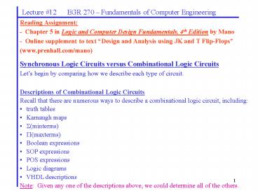
Lecture 12 EGR 270 Fundamentals of
Computer Engineering
Reading Assignment - Chapter 5 in Logic and
Computer Design Fundamentals, 4th Edition by
Mano - Online supplement to text Design and
Analysis using JK and T Flip-Flops (www.prenhall.
com/mano)
- Synchronous Logic Circuits versus Combinational
Logic Circuits - Lets begin by comparing how we describe each
type of circuit. - Descriptions of Combinational Logic Circuits
- Recall that there are numerous ways to describe a
combinational logic circuit, including - truth tables
- Karnaugh maps
- ?(minterms)
- ?(maxterms)
- Boolean expressions
- SOP expressions
- POS expressions
- Logic diagrams
- VHDL descriptions
- Note Given any one of the descriptions above,
we could determine all of the others.
2
Lecture 12 EGR 270 Fundamentals of
Computer Engineering
- Descriptions of Sequential Logic Circuits
- Similarly, there are numerous ways to describe a
sequential logic circuit, including - State diagrams
- State tables
- State equations and output equations
- Input equations (flip-flop input functions) and
output Equations - Logic diagrams
- VHDL descriptions
- Note Given any one of the descriptions above,
we could determine all of the others. - Some of these ways to describe sequential
circuits will now be introduced.
Finite State Machines (FSM) Sequential circuits
are also referred to as finite state machines.
The circuit operates by moving between a finite
number of pre-determined states.
3
Lecture 12 EGR 270 Fundamentals of
Computer Engineering
State Diagrams This is the most common way to
describe a sequential circuit. A state diagram is
somewhat like a flowchart that describes the
sequence to states through which the circuit
might progress. State a distinct event that is
to occur (one event in a sequence) Example A
state might be a single count in a counter. If a
counter counts 0, 1, 2, .. , 9 and then repeats,
then it has 10 unique states. If four flip-flops
were used to store the count, then the flip-flops
would store the values 1001 corresponding to
state 9. Example A state might be one step in
a machining operation (there might be 5 states
corresponding to the operations drill, ream,
counterbore, countersink, and polish). Example
A traffic light controller might have three
states Green, Yellow, and Red. Under certain
input conditions or at certain times, the
controller will change state.
4
Lecture 12 EGR 270 Fundamentals of
Computer Engineering
Encoding states Show how a binary code can be
stored in a set of flip-flops. In most cases,
Number of flip-flops needed log2(Number of
states)
Example Determine the number of states needed
in each case below
Description of circuit Number of flip-flops required
Circuit with 20 states
Traffic light controller
3-bit UP/DOWN counter
Decade counter
5
Lecture 12 EGR 270 Fundamentals of
Computer Engineering
There are two primary types of state diagrams
(state machines) Mealy state machine (Mealy
model) the output depends on the present state
and the inputs applied. Moore state machine
(Moore model) the output only depends on the
present state.
We will primarily use Mealy models
X
X/Y
C/Y
C
Moore Model
- Transition from one state to another depends on
the Input, X - Output, Y, is specified with the Present State
- Output, Y, depends only on the Present State
6
Lecture 12 EGR 270 Fundamentals of
Computer Engineering
Example Both a Mealy Model and a Moore Model
are used below to specify state machines that
will detect the occurrence of two 1s in a row.
Moore Model
Mealy Model
State A Zero 1s received State B One 1
received State C Two 1s received
State A Zero 1s received State B One 1
received
- Two states (one flip-flop)
- Output of 1 indicates that two inputs of 1
occurred in a row. - Output is not associated with a state, but with
the transition.
- Three states (two flip-flops)
- Output of 1 indicates that two inputs of 1
occurred in a row. - Output is associated with state C.
7
Lecture 12 EGR 270 Fundamentals of
Computer Engineering
Comparison of Mealy models and Moore models
Mealy Model Moore Model
Output depends on both the Present State and the Inputs Output depends only on the Present State
Specify output in transition Specify output in Present State
Generally requires fewer states Generally requires more states
Output may change immediately when input changes, so may change in the same clock cycle Output does not respond immediately to input change, but is synchronized with the clock
Reacts faster to inputs Safer
Most of our textbook examples and class examples will use Mealy models
8
Lecture 12 EGR 270 Fundamentals of
Computer Engineering
Examples of state diagrams
A) Modulo-5 (mod-5) counter
B) 3-bit Up/Down counter
C) Traffic Light Controller
9
Lecture 12 EGR 270 Fundamentals of
Computer Engineering
State Table A state table provides the same
information as the state diagram, but in tabular
form.
Example Determine the state table for the state
diagram shown below.
Is this a Mealy machine or a Moore machine?
10
Lecture 12 EGR 270 Fundamentals of
Computer Engineering
State Assignment Some state diagrams have states
indicated by letters or names because there is no
numeric value assigned to the states. As an
example, there are no natural numeric values for
the states in a circuit that controls a traffic
light (states, RED, YELLOW, and GREEN). In such
cases, numeric values must be assigned to each
state. In the case of the traffic light, 2 bits
are needed to encode the three states, but
various possible codes could be used. For
example, RED 00, YELLOW 01, and GREEN 10.
There are many other possible state assignments.
Which is the best assignment to use? We dont
know. This is a current research topic.
Example List possible state assignments for the
last problem and repeat the state table using one
of the state assignments.
11
Lecture 12 EGR 270 Fundamentals of
Computer Engineering
Determining the State Diagram from a Logic
Diagram The state diagram or state table can be
found from the logic diagram by assuming an
initial state, determining the corresponding
flip-flop input values, and then using the truth
table for the flip-flop to find the next state.
This information can be easily tabulated as in
the example below.
12
Lecture 12 EGR 270 Fundamentals of
Computer Engineering
Example Determine the state diagram for the
logic diagram shown below.
Present State/Inputs Present State/Inputs Present State/Inputs Flip-flop inputs Flip-flop inputs Flip-flop inputs Flip-flop inputs Next State Next State Output
x A B JA KA JB KB A B y
0 0 0
0 0 1
0 1 0
0 1 1
1 0 0
1 0 1
1 1 0
1 1 1
13
Lecture 12 EGR 270 Fundamentals of
Computer Engineering
- Sequential Circuit Design Methods
- Three specific methods will be covered for
designing synchronous sequential circuits - The Excitation Table method
- The State Equation method
- One-Hot method
- Excitation Table Method (also read the Online
supplement to text Design and - Analysis using JK and T Flip-Flops available at
www.prenhall.com/mano - Before covering the excitation table method, it
is useful to develop - the excitation tables for each type of flip-flop.
- Flip-flop Excitation Tables
- Truth table defines the output state based on
the inputs - Excitation table defines required inputs to
cause a transition from one state to another.
Example Complete the excitation table below for
the JK flip-flop
JK flip-flop truth table JK flip-flop truth table JK flip-flop truth table JK flip-flop excitation table JK flip-flop excitation table JK flip-flop excitation table JK flip-flop excitation table
J K Q(t 1) Q(t) Q(t 1) J K
0 0 Q 0 0
0 1 0 0 1
1 0 1 1 0
1 1 Q 1 1
14
Lecture 12 EGR 270 Fundamentals of
Computer Engineering
- Excitation table method Design Procedure
- Problem description.
- Obtain the state table.
- Use state assignment to assign binary values to
each state if they are symbolic. - Determine the number of flip-flops required and
assign a letter or number to each. - Determine the type of flip-flop to use (SR, JK,
D, or T). - Derive the circuit excitation table and output
table from the state table. - Simplify
- a) the circuit output functions
- b) the flip-flop input functions
- Draw the logic diagram.
Example Design a modulo-7 counter (counts 0 to
6 and repeats) using JK flip-flops.
15
Lecture 12 EGR 270 Fundamentals of
Computer Engineering
Flip-flop Excitation Tables
Q(t) Q(t1) J K S R D T
0 0 0 X 0 X 0 0
0 1 1 X 1 0 1 1
1 0 X 1 0 1 0 1
1 1 X 0 X 0 1 0
Circuit Excitation Table
Present States/Inputs Present States/Inputs Present States/Inputs Next State Next State Next State Flip-flop Inputs and Circuit Outputs Flip-flop Inputs and Circuit Outputs Flip-flop Inputs and Circuit Outputs Flip-flop Inputs and Circuit Outputs Flip-flop Inputs and Circuit Outputs Flip-flop Inputs and Circuit Outputs Flip-flop Inputs and Circuit Outputs
0 0 0
0 0 1
0 1 0
0 1 1
1 0 0
1 0 1
1 1 0
1 1 1
16
Lecture 12 EGR 270 Fundamentals of
Computer Engineering
Flip-flop Input Functions and Circuit Output
Functions
Recommended
CrystalGraphics Presentations


