
Thermal Noise Limit in Frequency Stabilization of Lasers with Rigid Cavities - PowerPoint PPT Presentation
1 / 1
Title:
Thermal Noise Limit in Frequency Stabilization of Lasers with Rigid Cavities
Description:
Fundamental physics tests. Interferometric measurement ex.) LISA, LIGO... Thermal noises are one of the fundamental phenomena in physics. ... – PowerPoint PPT presentation
Number of Views:26
Avg rating:3.0/5.0
Title: Thermal Noise Limit in Frequency Stabilization of Lasers with Rigid Cavities
1
Thermal Noise Limit in Frequency Stabilization of
Lasers with Rigid Cavities
Kenji Numata, Amy Kemery, and Jordan Camp
Exploration of the Universe Division, Code 663,
NASA/Goddard Space Flight Center, Greenbelt,
Maryland 20771
We evaluated thermal noise (Brownian motion) in a
rigid reference cavity used for frequency
stabilization of lasers, based on the mechanical
loss of cavity materials and the numerical
analysis of the mirror-spacer mechanics with the
direct application of the fluctuation dissipation
theorem. This noise sets a fundamental limit for
the frequency stability achieved with a rigid
frequency-reference cavity, of order 1Hz/rtHz
(0.01Hz/rtHz) at 10mHz (100Hz) at room
temperature. This level coincides with the
world-highest level stabilization results. (Phys.
Rev. Lett. 93 (2004) 250602)
- Experiment to measure Q
- Frequency stabilization of lasers
- The cavity material is polished on every surface
and suspended to avoid any surface and support
loss. The internal mode is excited by an
electrostatic actuator or a PZT actuator, and its
decay is measured by a Michelson interferometer
(miniature version of LISA, shown in the photo).
The decay time gives us the Q factor of the
material.
- Lasers have a wide range of applications
including - Optical frequency standards
- High resolution spectroscopy
- Fundamental physics tests
- Interferometric measurement ex.) LISA, LIGO...
- The use of a rigid cavity is a very common
technique in many fields. This technique is
required to suppress laser frequency noise, which
hinders us from performing sensitive
measurements. The use of a rigid cavity is a
basic design for LISA as well. - LISAs frequency stabilization scheme
- Pre-stabilization with rigid cavity gain106
(30Hz/rtHz) - Arm locking gain104
- Post processing (TDI) gain103
- Sample preparation the samples are coated with
gold to get reflected light, which is required
for interferometric measurement, from the
surface. - We measured several low CTE materials. They
showed much lower Q factors than, for example,
fused silica. The low Q enlarges thermal noise,
if these materials are used as cavity materials.
In the measured frequency range, from a few kHz
to 100kHz, a frequency dependence of loss was not
observed. Therefore, the structural damping model
was adopted for the analysis. - ULE Q6.1x104
- Zerodur Q3.1x103
- Clearceram (Z-HS) Q2.3x103
- A Thermal noise in a rigid cavity
- Thermal noises are one of the fundamental
phenomena in physics. Based on statistical
physics, Callen related the spectrum of random
motion to loss in a system, obtaining the
fluctuation dissipation theorem (FDT). - Frequency stability achieved with these FP
cavities is dependent on the stability of cavity
length. However, thermal noise (Brownian motion)
of the cavity has never been evaluated
rigorously. - We evaluated this noise by using the
Fluctuation-Dissipation Theorem (FDT). To apply
the FDT, we needed to calculate dissipated energy
in the cavity under an applied force. (It is
similar to measuring Joule heat from a resistance
under a applied voltage to estimate its thermal
noise.) We calculated it based on - Experimentally measuring the Q factor of cavity
materials - Calculation of strain energy using FEM (dynamical
Levins approach)
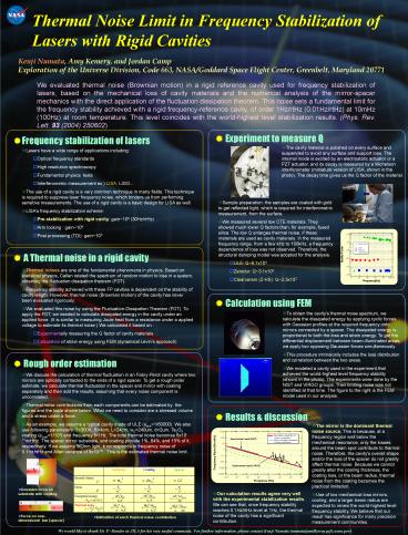
- Calculation using FEM
- To obtain the cavity's thermal noise spectrum, we
calculate the dissipated energy by applying
cyclic forces with Gaussian profiles at the
required frequency onto mirrors connected by a
spacer. The dissipated energy is proportional to
both the loss and strain energy. To get the
differential displacement between
beam-illuminated areas, we apply two opposing
Gaussian forces simultaneously. - This procedure intrinsically includes the loss
distribution and correlation between the two
areas. - We modeled a cavity used in the experiment that
achieved the world-highest level frequency
stability (shown in the photo). The experiments
were done by the NIST and VIRGO groups. Their
limiting noise was not identified at that time.
The figure to the right is the FEM model used in
our analysis.
- Rough order estimation
- We discuss the calculation of thermal fluctuation
in an Fabry-Perot cavity where two mirrors are
optically contacted to the ends of a rigid
spacer. To get a rough order estimate, we
calculate thermal fluctuation in the spacer and
mirror with coating separately and then add the
results, assuming that every noise component is
uncorrelated. - Thermal noise contributions from each components
can be estimated by the figures and the table
shown below. What we need to consider are a
stressed volume and a stress under a force. - As an example, we assume a typical cavity made of
ULE (fsub1/60000). We also use following
parameters T300K, R4cm, L24cm, w0240um,
d2um, Ta2O5 coating (fcoat1/104) and frequency
f1Hz. The total thermal noise becomes
6x10-17m/rtHz. The spacer mirror substrate, and
coating provide 1, 84, and 15 of it,
respectively. If we assume 563nm light, it
corresponds to frequency noise of 0.1Hz/rtHz and
Allan variance of 5x10-16. This is the estimated
thermal noise limit.
- Results discussion
- The mirror is the dominant thermal noise source.
This is because, at a frequency region well below
the mechanical resonance, only the losses around
the beam spot contribute to thermal noise.
Therefore, the cavity's overall shape and/or the
loss of the spacer do not greatly affect thermal
noise. Because we cannot greatly alter the
coating thickness, the coating loss, or the beam
radius, thermal noise from the coating becomes
the practical limitation. - Use of low mechanical loss mirrors, cooling, and
a larger beam radius are expected to renew the
world-highest level frequency stability. We
believe that our result has significance for many
precision measurement communities.
- Gaussian force on substrate with coating
- Our calculation results agree very well with the
experimental stabilization results. We can see
that, once frequency stability reaches 0.1Hz/rtHz
level at 1Hz, the thermal noise of the cavity has
a significant contribution.
- Force on one-dimensional bar (spacer)
- Estimation of each thermal noise contribution
We would like to thank Dr. P.Bender in JILA for
his very useful comments. For further
information, please contact Kenji Numata
(numata_at_milkyway.gsfc.nasa.gov).
Recommended
CrystalGraphics Presentations


