
ead%20aeronautics PowerPoint PPT Presentation
Title: ead%20aeronautics
1
?
ead aeronautics
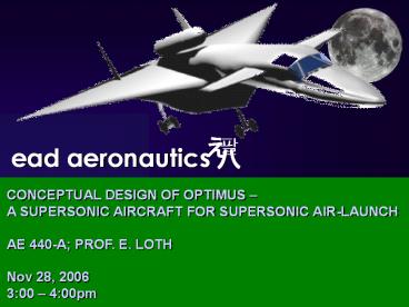
CONCEPTUAL DESIGN OF OPTIMUS A SUPERSONIC
AIRCRAFT FOR SUPERSONIC AIR-LAUNCH AE 440-A
PROF. E. LOTH Nov 28, 2006 300 400pm
2
ead aeronautics
TEAM MEMBERS
- Nathan Jung Her (Structures)
- Calvin Lee (Stability and Control)
- Seiji Matsushita (Propulsion)
- Phillip Robinson (Costs Con/Ops)
- Janice Quek (Aerodynamics)
- Wei Ren Quah (Config., Weights and Balance)
- Patrick Woo (T.L.) (Performance)
3
ead aeronautics
INTRODUCTION
- Introduction
- - Air-launch for more efficient space access
suggested - Request for Proposal (RFP)
- - Air breathing aircraft to air-launch Falcon 1
rocket - - Launch occurs at altitude of at least 50,000
ft - - 2 lt Mach no. lt 3
- - Takeoff from a runway in the U.S.
- - Launch occurs at distance of at least 200
miles offshore - - launch angle ? 25(3 M)
4
ead aeronautics
TEAM THEME
- Balance between Cost and Performance
- Performance Payload launch speed
- - higher launch speed higher delta V gain
- Design concepts and selection process
- Specialty areas
5
ead aeronautics
DESIGN CONCEPTS
- 14 design concepts were compared
1 2 3 4 5 6 7
Fuselage Flying wing, Swept/Delta Cylindrical Cylindrical Cylindrical Cylindrical blended Cylindrical Flying clamp
Wing Flying wing, Swept/Delta Top, Delta, withCanards Mid, Swept /Delta Low, Delta with Canards Mid, Delta Top, Variable Top to Mid
Tail Twin winglets Conventional Twin winglets Twin verticle tail Twin verticle tail Conventional Conventional
Landing Gear Tricyle Tricycle Tricycle Tricycle Tricycle Mult-bogey Multi-bogey
Engines Turbofan Turbofan Turbojet Turbojet Turbojet Turbofan Turbofan
Payload Captive on Top Captive on Bottom Captive on Top Captive on Top Internal, Captive on Bottom Internal, Captive on Bottom Captive on Bottom
6
ead aeronautics
DESIGN CONCEPTS
8 9 10 11 12 13 14
Fuselage Cylindrical Blended, Mid, Variable Blended, Mid, Delta Blended, Mid, Delta Flying wing, Delta Cylindrical blended Cylindrical
Wing Top, Swept Blended, Mid, Variable Blended, Mid, Delta Blended, Mid, Delta Flying wing, Delta Low, Swept Low, Swept
Tail Conventional Conventional Twin verticle tail Conventional V-tail Conventional V-tail
Landing Gear Tricycle Multi-bogey Tricycle Multi-bogey Tricycle Tricycle Tricycle
Engines Turbojet Turbojet Turbojet Turbojet Turbojet Turbojet Turbojet
Payload Internal/ Captive on Bottom Captive on Bottom Captive on Top Captive on Bottom Captive on Top Front Captive on Top
7
ead aeronautics
DESIGN CONCEPTS
- Eliminate designs with the following attributes
- - Variable wing geometries
- - Internal/external payload carrying method
- - Nose forward carrying method
- Justifications
- - penalty of weight
- - complexity
- - chance of failure
- - maintenance
- - stability
8
ead aeronautics
DESIGN CONCEPTS
- Group remaining design concepts with morphology
1 2 3 4 5 6 7 8
Fuselage Flying wing, Swept/ Delta Cylindrical Cylindrical Flying clamp Cylindrical Flying wing, Delta Flying Wing, Mid, Delta Cylindrical
Wing Flying wing, Swept/ Delta Top, Delta, With Canards Mid, Swept/ Delta Top to Mid Low, Delta With Canards Flying wing, Delta Flying Wing, Mid, Delta Low, Swept
Tail Twin winglets Conventional Twin winglets Conventional Twin verticle tail V-tail Conventional V-tail
Landing Gear Tricyle Tricycle Tricycle Multi-bogey Tricycle Tricycle Multi-bogey Tricycle
Engines Turbofan Turbofan Turbojet Turbofan Turbojet Turbojet Turbojet Turbojet
Payload Captive on Top Captive on Bottom Captive on Top Captive on Bottom Captive on Top Captive on Top Captive on Bottom Captive on Top
9
ead aeronautics
DESIGN CONCEPTS
10
ead aeronautics
CONCEPT SELECTION
Concept Selection Criteria Concept Selection Criteria Concept Selection Criteria Concept Selection Criteria
Criterion Design Concept 1 Design Concept 2 Design Concept 3
Structure 1 3 2
Aerodynamics 1 2 3
GTOW 2 1 3
Stability 2 3 1
Fuel Consumption 2 1 3
Propulsion 1 3 2
Costs 2 1 3
Total 11 14 17
11
ead aeronautics
DESIGN CONCEPTS
3
2
1
12
?
ead aeronautics
CONFIGURATION, WEIGHTS BALANCE
13
ead aeronautics
CONCEPT SELECTION
Concept Selection Criteria Concept Selection Criteria Concept Selection Criteria Concept Selection Criteria
Criterion Design Concept 1 Design Concept 2 Design Concept 3
Structure 1 3 2
Aerodynamics 1 2 3
GTOW 2 1 3
Stability 2 3 1
Fuel Consumption 2 1 3
Propulsion 1 3 2
Costs 2 1 3
Total 11 14 17
14
ead aeronautics
DESIGN CONCEPT 1
Front View
Top View
- Delta Wings
- - wing's leading edge remains
- behind shock wave
- - high stall angle
- - simplicity
- Canards
- - more statically stable
- - reduces lift-induced drag
- Captive on top
Side View
15
ead aeronautics
DESIGN CONCEPT 2
Front View
Top View
- Delta Wings
- - wing's leading edge
- remains behind shock
- wave
- - high stall angle
- - simplicity
- Flying Wing
- Captive on top
Side View
16
ead aeronautics
DESIGN CONCEPT 3
Front View
Top View
- Swept Wings
- - reduces drag
- - spanwise flow
- Captive on top
Side View
17
INITIAL SIZING
ead aeronautics
Mission Profile
50,000 ft
30,000 ft
30,000 ft
10
0. Start 1. Warm-up and Take-off 2. Climb
3. Cruise out
4. Climb 5. Dash 6. Launch 7.
Descend
8. Cruise in 9. Descend 10. Land
18
INITIAL SIZING
ead aeronautics
Design Concept 1 Design Concept 1 Mach number Altitude (ft) Range (ft) Wi/(i-1)
0 Start - 0 - -
1 Warm-up and Take-off - 0 - 0.9700
2 Climb (to 30,000ft) - 30,000 - 0.9850
3 Cruise out 0.8 30,000 1,056,000 0.9299
4 Climb (to 50,000ft) - 50,000 - 0.9850
5 Dash (for 10 mins) 2.5 50,000 1,640,419 0.9575
6 Payload Drop 2.5 50,000 - 1.0000
7 Descend (to 30,000ft) - 30,000 - 0.9900
8 Cruise in 0.8 30,000 2,696,419 0.8305
9 Descend - 0 - 0.9900
10 Land - 0 - 0.9950
GTOW 314,086 lbs
19
INITIAL SIZING
ead aeronautics
Design Concept 2 Design Concept 2 Mach number Altitude (ft) Range (ft) Wi/(i-1)
0 Start - 0 - -
1 Warm-up and Take-off - 0 - 0.9700
2 Climb (to 30,000ft) - 30,000 - 0.9850
3 Cruise out 0.8 30,000 1,056,000 0.9484
4 Climb (to 50,000ft) - 50,000 - 0.9850
5 Dash (for 10 mins) 2.5 50,000 1,640,419 0.9471
6 Payload Drop 2.5 50,000 - 1.0000
7 Descend (to 30,000ft) - 30,000 - 0.9900
8 Cruise in 0.8 30,000 2,696,419 0.8734
9 Descend - 0 - 0.9900
10 Land - 0 - 0.9950
GTOW 280,576 lbs
20
ead aeronautics
INITIAL SIZING
Design Concept 3 Design Concept 3 Mach number Altitude (ft) Range (ft) Wi/(i-1)
0 Start - 0 - -
1 Warm-up and Take-off - 0 - 0.97
2 Climb (to 30,000ft) - 30000 - 0.985
3 Cruise out 0.8 30000 1056000 0.9187
4 Climb (to 50,000ft) - 50000 - 0.985
5 Dash (for 10 mins) 2.5 50000 1640419 0.9666
6 Payload Drop 2.5 50000 - 1
7 Descend (to 30,000ft) - 30000 - 0.99
8 Cruise in 0.8 30000 2696419 0.8053
9 Descend - 0 - 0.99
10 Land - 0 - 0.995
GTOW 336,306 lbs
21
WEIGHT SUMMARY
ead aeronautics
Design Concept 1 Design Concept 2 Design Concept 3
GTOW (lbs) 314,086 280,576 336,306
Empty Weight (lbs) 109,526 96,627 118,274
Empty Weight Fraction 0.431 0.438 0.428
Mission Fuel Weight (lbs) 84,113 63,624 97,797
Fuel Weight Fraction 0.331 0.2884 0.3539
22
CONFIGURATION OF OPTIMUS
ead aeronautics
C.G. of Engines 128.1 ft
C.G. of Fuel 75 ft
Span 95.71 ft
660
Overall C.G. 87.1 ft
C.G. OF Empty Weight of Aircraft
80.75 ft
C.G. of Falcon 1 87.1 ft
22
Length of Aircraft 154.79 ft
23
?
ead aeronautics
AERODYNAMICS
24
ead aeronautics
CONCEPT SELECTION
Concept Selection Criteria Concept Selection Criteria Concept Selection Criteria Concept Selection Criteria
Criterion Design Concept 1 Design Concept 2 Design Concept 3
Structure 1 3 2
Aerodynamics 1 2 3
GTOW 2 1 3
Stability 2 3 1
Fuel Consumption 2 1 3
Propulsion 1 3 2
Costs 2 1 3
Total 11 14 17
25
ead aeronautics
NUMERICAL COMPARISONS
Property Design Concept 1 Design Concept 2 Design Concept 3
Property Design Concept 1 Design Concept 2 Design Concept 3
Description Strategic Bomber Flying Wing Conventional Configuration
Maximum Speed Mach 3.1 Mach 0.67 Mach 2.21
Wing Type Delta Delta Aft Swept
Wing Area 6296 5000 6200
Wing Span 105 172 39.9
Sweep Back Angle 66 33 26.6
Aspect Ratio 1.75 5.9168 8
Fuselage Length 185ft 69ft 58.67ft
L/D 8.33 7.03 12.8
CD0 0.013 0.027 0.023
e 0.66 0.7 0.6
CD 0.03 0.03 0.04
CL 0.25 0.211 0.5
Aircraft in Industry XB-70 B-2 Spirit C-5A
25
26
ead aeronautics
WING GEOMETRY
- Delta Wing Geometry versus Aft-Swept Wing
Geometry - Performance Characteristics
- Theme and Team Goals
Balance between COST and PERFORMANCE
Wing Type Delta Delta Aft-Swept
CD 0.03 0.03 0.04
CL 0.25 0.211 0.5
Lift 494485 331437 973892
Drag 59338 47123 77911
27
ead aeronautics
ASPECT RATIO
- Importance of Aspect Ratio
- Wing tip Vortices
- Reducing Induced Drag
- Reducing Wave Drag
Key Optimizing Aspect Ratio of Wing
28
ead aeronautics
TRADE STUDY EFFECT OF AR ON CD
- Speeds at Mach 0.8 and Mach 2.5
- Trend
- At Mach 0.8, CD decreases as aspect ratio
increases. - At Mach 2.5, CD increases as aspect ratio
increases
29
ead aeronautics
NUMERICAL ANALYSIS
Using the component build-up method,
30
ead aeronautics
MISSION MODEL
Drag Take-off 59,032lb Subsonic
Cruise 58,800lb Dash
217,695lb After Launch 209,468lb Land
43,246lb
31
ead aeronautics
MISSION MODEL
32
ead aeronautics
FUSELAGE DESIGN
- At supersonic speeds, one of the greatest
challenges is to minimize wave drag (pressure
drag due to formation of shocks) - Related to total cross-sectional area of aircraft
33
ead aeronautics
CONCLUSION FUTURE CONSIDERATIONS
- Preliminary analysis was performed on all 3
aircraft design concepts. - Detailed numerical analysis was conducted of the
Optimus. - FUTURE CONSIDERATIONS
- Methods to reduce drag.
- A more refined lift drag model.
- Airfoil Selection.
34
?
ead aeronautics
PERFORMANCE
35
ead aeronautics
CONCEPT SELECTION
Concept Selection Criteria Concept Selection Criteria Concept Selection Criteria Concept Selection Criteria
Criterion Design Concept 1 Design Concept 2 Design Concept 3
Structure 1 3 2
Aerodynamics 1 2 3
GTOW 2 1 3
Stability 2 3 1
Fuel Consumption 2 1 3
Propulsion 1 3 2
Costs 2 1 3
Total 11 14 17
36
FUEL CONSUMPTION
ead aeronautics
Mission Profile
50,000 ft
30,000 ft
30,000 ft
10
0. Start 1. Warm-up and Take-off 2. Climb
3. Cruise out
4. Climb 5. Dash 6. Launch 7.
Descend
8. Cruise in 9. Descend 10. Land
37
ead aeronautics
FUEL CONSUMPTION
Design Concept 1 Design Concept 1 Mach number Altitude (ft) Range (ft) Wi/(i-1) Fuel burned (lb)
0 Start - 0 - - -
1 Warm-up and Take-off - 0 - 0.97 7,624
2 Climb (to 30000ft) - 30,000 - 0.985 3,697
3 Cruise out 0.8 30,000 1,056,000 0.9299 17,020
4 Climb (to 50000ft) - 50,000 - 0.985 3,387
5 Dash (for 10 mins) 2.5 50,000 1,640,419 0.9575 9,452
6 Payload Drop 2.5 50,000 - 1 0
7 Descend (to 30000ft) - 30,000 - 0.99 2,129
8 Cruise in 0.8 30,000 2,696,419 0.8305 35,732
9 Descend - 0 - 0.99 1,751
10 Land - 0 - 0.995 867
38
ead aeronautics
FUEL CONSUMPTION
Design Concept 2 Design Concept 2 Mach number Altitude (ft) Range (ft) Wi/(i-1) Fuel burned (lb)
0 Start - 0 - - -
1 Warm-up and Take-off - 0 - 0.97 7,908
2 Climb (to 30000ft) - 30,000 - 0.985 3,835
3 Cruise out 0.8 30,000 1,056,000 0.9299 17,655
4 Climb (to 50000ft) - 50,000 - 0.985 3,513
5 Dash (for 10 mins) 2.5 50,000 1,640,419 0.9575 9,804
6 Payload Drop 2.5 50,000 - 1 0
7 Descend (to 30000ft) - 30,000 - 0.99 2,209
8 Cruise in 0.8 30,000 2,696,419 0.8305 37,065
9 Descend - 0 - 0.99 1,816
10 Land - 0 - 0.995 899
39
ead aeronautics
FUEL CONSUMPTION
Design Concept 3 Design Concept 3 Mach number Altitude (ft) Range (ft) Wi/(i-1) Fuel burned (lb)
0 Start - 0 - - -
1 Warm-up and Take-off - 0 - 0.97 15,498
2 Climb (to 30000ft) - 30,000 - 0.985 7,517
3 Cruise out 0.8 30,000 1,056,000 0.9299 34,601
4 Climb (to 50000ft) - 50,000 - 0.985 6,885
5 Dash (for 10 mins) 2.5 50,000 1,640,419 0.9575 19,214
6 Payload Drop 2.5 50,000 - 1 0
7 Descend (to 30000ft) - 30,000 - 0.99 4,329
8 Cruise in 0.8 30,000 2,696,419 0.8305 72,641
9 Descend - 0 - 0.99 3,559
10 Land - 0 - 0.995 1,762
40
ead aeronautics
FUEL CONSUMPTION SUMMARY
Design Concept 1 Design Concept 2 Design Concept 3
Fuel burned (lbs) 94,264 84,704 166,006
Mission Fuel Weight (lbs) 97,092 87,245 170,986
- Assuming no payload drop so the Falcon 1 rocket
can be - safely returned
- Although Design Concept 2 consumes the least
amount - of fuel, Design Concept 1 is chosen
41
ead aeronautics
CONSTRAINT ANALYSIS
- Take-off with 50ft clearance from 15,000 ft
runway at sea level - Landing distance of 3,000 ft
- Cruises at M 0.8 at 30,000 ft
- Dashes at M 2.5 at 50,000 ft
42
ead aeronautics
CONSTRAINT ANALYSIS
43
ead aeronautics
CONCLUSION AND FURTHER ANALYSIS
- Thrust to Weight ratio of 0.9 is required for
dash constraint - Enough thrust must be provided!
- Further analysis in the next semester
- - Maximum dash speed
- - Maximum altitude
44
?
ead aeronautics
PROPULSION
45
ead aeronautics
CONCEPT SELECTION
Concept Selection Criteria Concept Selection Criteria Concept Selection Criteria Concept Selection Criteria
Criterion Design Concept 1 Design Concept 2 Design Concept 3
Structure 1 3 2
Aerodynamics 1 2 3
GTOW 2 1 3
Stability 2 3 1
Fuel Consumption 2 1 3
Propulsion 1 3 2
Costs 2 1 3
Total 11 14 17
46
ead aeronautics
COMPARISONS
- Design Concept 1 (BEST)
- - Able to carry more engines
- Design Concept 2 (WORST)
- - Limit of engine size and
- numbers
- - Very high thrust engine
- needed
- Design Concept 3 (GOOD)
- - Limit of engine size and
- numbers
47
ead aeronautics
TURBOJETS
- Concorde
- (Rolls-Royce/SNECMA Olympus 593 Mk 602 turbojets
) - XB-70
- (General Electric J-93 afterburning turbojets
Peter, St. James, The Histroy of Aircraft Gas
Turbine Engine Development in the United States
A Tradition of Excellence 1 st ed., The
International Gas Turbine Institute of ASME.,
1999, pp.430-569
48
ead aeronautics
TURBOFANS
- F-15
- (Pratt Whitney F100-220 afterburning turbofans
) - F-111F
- (Pratt Whitney TF30-111 afterburning turbofans)
Peter, St. James, The Histroy of Aircraft Gas
Turbine Engine Development in the United States
A Tradition of Excellence 1 st ed., The
International Gas Turbine Institute of ASME.,
1999, pp.430-569
49
ead aeronautics
ENGINES DATA
- Turbojets and Turbofans with Afterburner (AB) at
Sea Level Condition
Max/Normal Thrust (lb) pc Length (in) Diameter (in) Weight (lb) a
Olympus 593 38,000/32,000 11 280 47.75 7,000 NA
J93 28,000/17,700 13.85 236.3 54.2 5,220 NA
F110-220 23,830/14,670 25 191.2 46.5 3,200 0.6
TF30-P-111 25,100/14,560 21.8 241.7 49 3,999 0.73
Mattingly, D. Jack, Elements of Gas Turbine
Propulsion, 1 st ed., McGraw-Hill, Inc., 1996,
pp.240-265
50
ead aeronautics
SFC vs. Mach
51
ead aeronautics
SFC vs. Mach
52
ead aeronautics
SFC vs. Altitude
53
ead aeronautics
SFC vs. Altitude
54
ead aeronautics
WHICH IS BEST?
- Turbojets with AB
- - Higher thrust
- - SFC is low in dash
- with AB
- Turbofan with AB
- - Lower thrust
- - SFC is low in cruise
- without AB
Turbojets with AB are better
55
ead aeronautics
FINAL DECISION
Max/Normal Thrust (lb) SFC (lbm/hr)/lbf SFC (lbm/hr)/lbf
Max/Normal Thrust (lb) Cruise Dash
Olympus 593 38,000/32,000 1.169 1.4
J93 28,000/17,700 0.934 1.45
- J93 Turbojet with Afterburner is BEST!
56
ead aeronautics
FURTHER ANALYSIS
- Find more recent engines
- - Turbojets and Turbofans with AB
- Design Fuel System and Fuel Tanks
- General Propulsion System Integration Losses
57
?
ead aeronautics
STABILITY CONTROL
58
ead aeronautics
CONCEPT SELECTION
Concept Selection Criteria Concept Selection Criteria Concept Selection Criteria Concept Selection Criteria
Criterion Design Concept 1 Design Concept 2 Design Concept 3
Structure 1 3 2
Aerodynamics 1 2 3
GTOW 2 1 3
Stability 2 3 1
Fuel Consumption 2 1 3
Propulsion 1 3 2
Costs 2 1 3
Total 11 14 17
59
ead aeronautics
DESIGN CONCEPT 1
- Cons
- -Canards are not as common as aft tails
- -May need high lift airfoil for canard
- -Difficulty in using flaps
- Pros
- -Canards can be made to stall before wing
- -Enhanced roll rate from elevons
Rank 2nd
60
ead aeronautics
DESIGN CONCEPT 2
- Cons
- -Flying wings inherently unstable
- -Requires complex reflexed trailing edge for
static stability (inefficient) - -May require automatic flight control systems
- -Complicated wing planforms with varying chords
and twist to achieve restoring moment
Rank 3rd
61
ead aeronautics
DESIGN CONCEPT 3
- Cons
- -V-Tail requires a more complex control system
- -Significant flight testing needed to program
V-Tail - Pros
- -Aft tail is a time tested design
- -Plenty of historical data to compare design
space
Rank 1st
62
ead aeronautics
INITIAL SIZING
- Auxiliary Lifting Surfaces
- - Used historical tail volumes of Large
cargo/transport - aircraft
- - Fin and canard airfoil is NACA 0012
- Control Surface Sizing
- - MILSPEC roll rate for Class III aircraft is 30
degrees in - 1.5 seconds
- - Initial sizing based on historical data and
guidelines - Final Sizing based on dynamic analysis
63
ead aeronautics
STATIC MARGIN
- Neutral point calculation completed to determine
acceptable CG range - 5-10 Static Margin for Large Bomber/Cargo
Aircraft - Canard experiences upwash as opposed to tail
which experiences downwash
Static Margin
64
ead aeronautics
LONGITUDINAL STATIC STABILITY
- Longitudinal stability most vital to airplane
- Placing CG ahead of neutral point satisfies one
of two conditions for stability - Must check to see that CM0 is greater than zero
- Assumed virtually no CG shift from rocket release
Longitudinal Static Stability
65
ead aeronautics
TRIM ANALYSIS
- Used graphical method rather than iterative
computational process. - Trim analysis shows aircraft can be trimmed for
many different CL. - Subsonic and supersonic trim very similar due to
comparable CMa . - Positive elevon deflection produces upload on
canard.
66
ead aeronautics
TRIM ANALYSIS
Trim Analysis for Subsonic Cruise
67
ead aeronautics
LATERAL STATIC STABILITY
- Coupled analysis on roll and yaw
- Meets the typical yaw moment derivative values as
described by Raymer.
Lateral-Directional Stability Derivatives
68
ead aeronautics
FURTHER ANALYSIS
- Must examine dynamic stability and control
characteristics - Investigate high lift airfoils for canard
- Flexibility Effects
- Engine out analysis
- Ground effects
- Adverse yaw and differential control surface
inputs
69
ead aeronautics
STRUCTURES
70
ead aeronautics
CONCEPT SELECTION
Concept Selection Criteria Concept Selection Criteria Concept Selection Criteria Concept Selection Criteria
Criterion Design Concept 1 Design Concept 2 Design Concept 3
Structure 1 3 2
Aerodynamics 1 2 3
GTOW 2 1 3
Stability 2 3 1
Fuel Consumption 2 1 3
Propulsion 1 3 2
Costs 2 1 3
Total 11 14 17
71
ead aeronautics
STRUCTURAL REQUIREMENT
- Speed Mach 2.5
- Altitude 50,000 ft
- - The speed and the altitude requirements yield
- - Kinetic heating ranges from -25ºF to 450ºF
- - Thermal cycling under moisture and radiation
impact - Payload 59,960 lb
- Must have strong mounts for the payload
72
ead aeronautics
STRUCTURAL SELECTION
- Selection criteria
- Feasibility of new concepts
- Structural strength
- Minimum Weight
- Ease of manufacturing
73
ead aeronautics
STRUCTURAL SELECTION
- Design Concept 1
Pros Cons
Delta wing straight linear structures (spars) enough room for fuel, landing gear, and structure Curved longerons for the fuselage Difficulty placing the rocket
74
ead aeronautics
STRUCTURAL SELECTION
- Design Concept 2
Pros Cons
Simple geometry for spars and ribs (straight path) Smaller structure (light weight) Weight is distributed along the span of the wing Large cutouts for landing gear (not enough space for both spars and cutout) Extra bulkhead needed for engine mounts
75
ead aeronautics
STRUCTURAL SELECTION
- Design Concept 3
Pros Cons
Engine inlet structure supports the wing loading Bulkhead in the aft fuselage shares the load with engines and landing gears Excessive structure (fuselage) Wing loading concentrated at the smaller wing root than delta wing
76
ead aeronautics
MATERIALS
Titanium
Stainless Steel Honeycomb
Steel
77
ead aeronautics
BULKHEADS AND LOAD PATH
Rocket Mounts
Forward Bulkhead
Landing Gear Mounts
Engine Mounts
78
ead aeronautics
V-n DIAGRAM
Vdive 3136fps
n7
n
n-3
V (fps)
79
ead aeronautics
CONCLUSION AND FUTURE ANALYSIS
- Conclusion
- - Delta wing structure was chosen
- - No complex composites were used to lower
the - cost
- Future Analysis
- - Finite Element Method (FEM) analysis should
be - conducted
- - Investigate the stress of the rocket
attachment fittings - - Design landing gear
80
?
ead aeronautics
COSTS
81
ead aeronautics
CONCEPT SELECTION
Concept Selection Criteria Concept Selection Criteria Concept Selection Criteria Concept Selection Criteria
Criterion Design Concept 1 Design Concept 2 Design Concept 3
Structure 1 3 2
Aerodynamics 1 2 3
GTOW 2 1 3
Stability 2 3 1
Fuel Consumption 2 1 3
Propulsion 1 3 2
Costs 2 1 3
Total 11 14 17
82
ead aeronautics
COST ANALYSIS
- Used RAND DAPCA IV Model
- - Find approximate unit price
- Hours needed Engineering, Tooling, Manufacturing
- Cost estimated Develop, Flight Test,
Manufacturing, Material, Engineering production
83
ead aeronautics
DESIGN CONCEPT 1
- We 109,526 lbs
- Velocity M2.5 at 50,000 ft
- 1433 Knots
- Number Produced (Q) 5
- FTA3
- Neng40
- Thrust max 28,000 lbs
- GE J93 Turbojet w/ AB
84
ead aeronautics
DESIGN CONCEPT 2
- We 96,627 lbs
- Velocity M2.5 at 50,000 ft
- 1433 Knots
- Number Produced (Q) 5
- FTA3
- Neng40
- Thrust max 28,000 lbs
- GE J93 Turbojet w/ AB
85
ead aeronautics
DESIGN CONCEPT 3
- We 118,274 lbs
- Velocity M2.5 at 50,000 ft
- 1433 Knots
- Number Produced (Q) 5
- FTA3
- Neng40
- Thrust max 28,000 lbs
- GE J93 Turbojet w/ AB
86
ead aeronautics
ESTIMATED COST
Costs Design Concept 1 Design Concept 2 Design Concept 3
Total Cost (5 AC) 8,954,080,073 8,619,522,958 9,851,267,581
Total Cost (Individual) 1,790,816,015 1,723,904,592 1,970,253,516
87
ead aeronautics
DESIGN 1 - OPTIMUS
- Moderate expensive aircraft to build.
- Best performance capabilities for the best price
- Based off a similar design
- Marketable
88
ead aeronautics
CONCEPT/OPS
- Base Kennedy Space Center, Cape Canaveral, FL
- Fly out east of KSC
- Captive on top delivery
- ? 25 (3-M)
- ? 12.5
89
ead aeronautics
CONCLUSION
- Cost Estimation seems reasonable
- Moderately expensive out of the three
- Much cheaper than the traditional launches from
earth
90
?
ead aeronautics
CONCLUSION FUTURE PLANS
91
ead aeronautics
CONCLUSION FUTURE PLANS
- Highly versatile delivery aircraft and favored
in terms of Structure Stability - Optimus meets the RFP
- Optimus will provide an alternative method to
deliver rockets into orbit - Promote this idea to potential buyers,
hopefully expanding the market for this
innovative method to launch rockets into space. - Decrease thrust requirement by reducing drag.
Lower cost. Will be looked into next semester.
92
ead aeronautics
REFERENCES
- Jenkinson, L., Civil Jet Aircraft Design, AIAA,
1999 - Mattingly, D. Jack, Elements of Gas Turbine
Propulsion, 1 st ed., McGraw-Hill, Inc., 1996,
pp.240-265. - McCormick, B.W., Static Stability and
Control, Aerodynamics, Aeronautics, and Flight
Mechanics, 2nd ed, Wiley, New York, 1995, pp.
473-534. - Peter, St. James, The History of Aircraft Gas
Turbine Engine Development in the United States
A Tradition of Excellence 1 st ed., The
International Gas Turbine Institute of ASME.,
1999, pp.430-569 - Raymer, D.P., Aircraft Design A Conceptual
Approach, AIAA Education Series, 2002
93
ead aeronautics
Questions?
Recommended
