
Bob%20Gilliver%20MSC/ARIES%20European%20Product%20Marketing%20and%20Support PowerPoint PPT Presentation
Title: Bob%20Gilliver%20MSC/ARIES%20European%20Product%20Marketing%20and%20Support
1
(No Transcript)
2
(No Transcript)
3
Bob GilliverMSC/ARIES European Product Marketing
and Support Manager
4
- Geometry
- FE Analysis
- Optimization
- Mechanisms
- Plastics
- MSC/ARIES Positioning
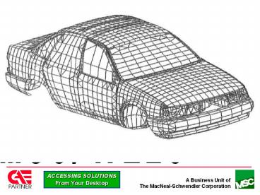
5
Geometry
- Full function ACIS based modeler
- Constraints
- full
- partial
- none
- ACIS data exchange
- AutoCAD
- Bentley
- Integraph
- HP
6
Geometry
- Modify dimensions
7
Geometry
- Parametric relationships
Modification by dimension
8
Geometry
- Complex solids
- Skin operator
- Sweep operator
- Extensive blending and chamfering
- Region operator to sub-divide geometry
- Map meshing
- Load footprint areas
- Symmetry
9
MSC/ARIES Base - Assemblies
- Visualization
- Packaging
- Clearance
- Interference
- Mass properties
10
MSC/ARIES Base - Mass Properties
11
Geometry - Regioning
12
Geometry - Regioning
13
Geometry - Regioning
14
Geometry - Regioning
15
Pre Release Solids Shelling
- Shelling of solids to thin walled solids
- Per face (uniform) thickness control
- Face exclusion to create open solids
- Full Parametrics support
- Not supported
- Spline faces (fillet, sweep, skin, spline
segments in curve based primitives, extrude with
draft ltarc segmentgt)
16
Analysis Of ACIS Imported Geometry
CAD
ARIES
17
Geometry Interface - ACIS
- Support for ACIS sat (ASCII) and sab (binary)
file formats - Allows bi-directional exchange of solids, surface
and wireframe - Currently the most reliable solids data exchange
format - Transfers geometry only
- No feature or history information
18
Geometry Interface - Autocad Import
19
Geometry Interface - Autocad Import
20
Geometry Interface - Autocad Import
Lin. Static Error Contours
21
Geometry Interface - Autocad Export
22
Geometry Interface - IGES Import
- Supports
- Wireframe
- Point, line, arc, composite curve, spline
(112,126), conics (104), copious data (106) - Surface
- Untrimmed (118, 120, 122, 128)
- Trimmed (144)
- Solid
- Solid BREP (186, 514, 510, 508, 504, 502,)
23
Geometry Interface - IGES Export
- Supports
- Wireframe
- Point, line, arc, composite curve, spline
(112,126), conics (104) - Solid/surface
- Decomposed to precise wireframe BREP
- Decomposed to surface collection (trimmed or
untrimmed - 128, 142, 144) - Text
- Hidden line removal
- Silhouette edge generation
24
Geometry Interface - DXF Import
- Wireframe
- Point, line, arc, polyline
- Text
25
Geometry Interface - DXF Export
- Supports
- Wireframe
- Point, line, arc, composite curve, spline
- Solid/surface
- Decomposed to precise wireframe BREP
- Text
- Hidden line removal
- Silhouette edge generation
26
Geometry Interfaces - STEP, VDAFS
- PDES/STEP AP203
- Import and export of solid/surface/wireframe data
- VDAFS
- Import and export of surface/wireframe data
- Data format that emphasizes surface transfer
- Used predominantly by European automotive industry
27
Geometry Interfaces -Stereolithography
- Translates solids into standard stl format
- Rapid manufacture for physical part prototyping
28
- Geometry
- FE Analysis
- Optimization
- Mechanisms
- Plastics
- MSC/ARIES Positioning
29
Load and Boundary Conditions
- LBCs applied to geometry or to nodes elements
- Supported loads
- Force, moment, pressure
- Gravity
- Velocity
- Translational
- Rotational
- Acceleration
- Translational
30
Load and Boundary Conditions
- Constant or functional varying magnitude
- Geometry based load and boundary conditions
survive geometry change
31
Load and Boundary Conditions
- Direction control for load/boundary conditions
- XYZ
- Radial
- Tangential
32
Load and Boundary Conditions
- Load case combination
- (5 load_1)
- (3 load_2)
33
FE Meshing
- Automeshing technology
- Edges -- 1D elements (beam, gap, rigid, spring)
- Surfaces -- quad dominant or all trias
- Volumes -- tets only
- Map meshing for surfaces and volumes
- 3/4 side surfaces, 5/6 face volumes
- Composite edge support
34
Auto Meshing
Solid Element Automesh
35
FE Meshing
- Adaptive mesh refinement
- Automatic mesh refinement to optimize mesh
density - Use with automatically generated h or p meshes
- Global or local refinement
- New mesh density based on current error versus
target error - Reduces mesh density related errors
36
2
1
Original mesh - 21 Error
Original mesh
4
3
Refined mesh - 7 Error
Automatic refinement
37
FE Meshing
- Direct creation of nodes/elements
- Extrude/revolve 1D to 2D, 2D to 3D
- Mirror
- Mesh editing
- Auto MPC connection of meshes between linear or
quad tets to linear hex
- Element quality checks
- Merge node
38
Results Review
- Display options
- Vector
- Contour
- Graph
- Animation
- Cutting plane
- Results in any coordinate system
- Data averaging control
- Results combination
- Error calculation
39
Linear Statics
- Loads constant with time
- Material assumed linear and perfectly elastic
- Results calculated
- Stress
- Displacement
- Strain
- Strain energy
- Reaction force
40
Normal Modes
- Calculates undamped natural modes of vibration
- Material assumed linear and perfectly elastic
- Results calculated (normalized)
- Stress
- Displacement
- Strain
- Strain energy
- Reaction force
41
Linear Buckling
- Calculates load factor for critical buckling
- Material assumed linear and perfectly elastic
- Results calculated
- Stress
- Displacement
- Strain
- Strain energy
- Reaction force
42
Non-Linear Statics
- Geometric non-linearity
- Change in stiffness associated with large
deformations - Load follows deformed shape
- Material non-linearity
- Bi-linear elastic/plastic with plastic strain, or
- Non-linear elastic, no plastic strain
- Compressive/tensile stress-strain curves can be
different
s
e
43
Non-Linear Statics
Non-linear Elastic Material
44
Structures-2 Non-Linear StaticsLoad Following
F
Undeformed
F
Deformed - load following
Deformed - load following
F
45
Linear Transient Dynamics
- Time varying geometry and finite element loads
- Structural and modal damping
- Results calculated for each time step
- Stress
- Displacement
- Strain
- Velocity
- Acceleration
- Reaction force
46
Heat Transfer
- Steady state and transient linear and non-linear
heat transfer - Heat transfer modes
- Conduction
- Free convection
- Forced convection
- Radiation
- Temperature and time dependent
- Heat flux
- Mass flow rate
47
Heat Transfer
48
MSC/ARIES To MSC/PATRAN
ARIES Created Geometry
49
MSC/ARIES To MSC/PATRAN
Imported ARIES Geometry in MSC/PATRAN
50
- Geometry
- FE Analysis
- Optimization
- Mechanisms
- Plastics
- MSC/ARIES Positioning
51
Optimization
- An Automated Process That
- Satisfies Your Design Objective
- Within Design Constraint(s)
- By Modifying Design Variables
52
Optimization - Overview
- 1 Design Objective
- minimize/maximize weight, frequency, load factor
- n Design Constraints - local and or global
- min/max stress, displacement, freq, load factor
- n Design Variables
- Dimensional variables
- Element shell thickness, Non Structural Mass
- Solve multiple constraints simultaneously
- Linear statics (with multiple load cases)
- Modal (per mode shape max/min control)
- Buckling analysis
53
Optimization - Overview
- Shape
- Geometry dimensions as design variables
- Sizing (element properties)
- Shell thickness, non-structural mass
- Design sensitivity
- Effect of a change in a design variable on
- Design Objective, Design Constraint(s)
- Shape and sizing can be combined
54
Initial Design
55
(No Transcript)
56
(No Transcript)
57
(No Transcript)
58
(No Transcript)
59
(No Transcript)
60
(No Transcript)
61
Final Design
62
Optimization - Application
- Build solid or surface geometry
- Associate dimension variables in Parametrics
- Use as design variables for Optimization
- Maintain design intent
- (Parameterize using DRP)
- Maintain design intent
- (Attach DRP model(s) to solids in Parametrics)
63
Optimization - Application
- Create finite element model
- Select Optimization application
- 1 Design Objective minimize/maximize
- weight, frequency, load_factor
- n Design Constraints - local and/or global
min/max stress, disp, freq, load factor - n Design Variables
- Dimensional,
- Shell thickness, Non Structural Mass
64
R2
R3
L2
DRP Model
L1
DEP INDEP R1 2 x R2 R2 R3
L2 R1 x 3
R1
Thick
Selecting Design Variables
65
Optimization - Results Review
- Post process in Optimization application
- Graph design objective/ constraint(s)/
variable(s) against design cycle - Display geometry at intermediate design cycles
- Review results of final design in FE_Results
- Standard results review process
- Animate between FEmodels across design cycles
66
67
P-Elements - Overview
- Automatically increases elements shape function
polynomial order during solution until
convergence - Convergence based on per element strain energy
difference between p-order changes - Mesh remains unchanged
68
P-Elements - Overview
- Each edge of each element has its p-order
independently controlled in MSC/NASTRAN
2
5
1
3
5
4
69
P-Elements - Application
- Supported element types
- Tetrahedron
- Brick
- Pentahedron (wedge)
- p-order min/max control
- Recommended p-order range 3-10
- Adaptivity automatically turns off below
specified von Mises stress or strain minimum - Turns off adaptivity for elements where stress
and or strain is negligible - Reduces CPU time and system resources
70
P-Elements - Application
Constrains shared edges to p-order 1
- Can mix h and p elements
- Use p-elements in areas where high accuracy
required, h-elements elsewhere
71
P-Elements - Application
- Hex to tet mesh connection works identically for
p-elements - Automatic (h-adaptive) mesh refinement supported
for automeshed p-elements - Uses ERROR DATASET calculated from FER TOOLKIT
error estimation
72
P-Elements - Results Review
- p-element results review identical to h-elements
- Can display final p element order contours
73
- Geometry
- FE Analysis
- Optimization
- Mechanisms
- Plastics
- MSC/ARIES Positioning
74
Mechanisms
- Two- and three-dimensional mechanism modeling
analysis and results review - Uses MDI/ADAMS Kinematics solver
- Solves motion of fully constrained (0 DOF)
kinematic systems i.e. the motion of the system
is completely constrained by applied motion(s)
and joint constraints
75
Mechanisms Pre Processing
- Create link geometry
- Geometry can be solid, surface or wireframe
- Add joints (supports all MDI/ADAMS joints)
- Add constant, harmonic, step, random motion
- Add motion constraints (e.g. cams), applied
forces, springs, gravity - Solve
Joints
Links
Contact
76
Mechanisms Results Review
- Animated motion of links
- Motion path of any point
- Joint reaction force/moment
- Rotational/translational link displacement,
velocity, acceleration - Clearance/interference between links
- Results interrogation in local static/dynamic
coordinate system
77
- Geometry
- FE Analysis
- Optimization
- Mechanisms
- Plastics
- MSC/ARIES Positioning
78
Plastics
- 3D mold fill analysis
- Uses Moldflow/Flowcheck solver
- Solves Will It Fill
- Fast analysis to calculate areas of fill /
no-fill / possible fill - Experiment with number of injection points/
location, material and part thickness - Solves Fill_Pattern
- Fill time
- Air trap location
- Weld line locations
79
Plastics
MSC/ARIES Created Solid
80
Plastics
Mold Fill Time Contours
81
82
Modular Configuration
83
Modular Configuration
84
MSC/ARIES Base
85
Optional Modules
86
Platform Support
WindowsNT Sun Solaris SGI HP IBM Digital Unix
87
Platform Requirements - WinNT
- Intel based (not Digital NT)
- Recommend gt Pentium 75MHz, 32Mb RAM
- 125 Mb swap space
- Any Microsoft supported graphics adapter in 256
color mode - WindowsNT
- Windows 3.1 and Windows95 not available
- Licensing
- Node-lock, standalone only
- No network license support
- Requires Ethernet adapter for licensing
88
Platform Requirements - Unix
- Supported Unix workstation
- 32Mb RAM
- 125 Mb swap space
- Licensing
- Node-lock, and
- Floating network license
89
- Geometry
- FE Analysis
- Optimization
- Mechanisms
- Plastics
- MSC/ARIES Positioning
90
MSC/ARIES Positioning
- Standalone Design and Analysis System
- Designed and analyzed in MSC/ARIES
- Analysis of ACIS Based Geometry
- Design built in CAD system
- Design geometry import into MSC/ARIES
- Analyzed in MSC/ARIES
- Focus on Ease-of-Use and Automation For...
91
MSC/ARIES Positioning
- Structural
- Thermal
- Mechanisms
- Plastic Molding Analysis
92
MSC/ARIESThe Flow of Development
Product
Almost all design concepts will be decided
93
Positioning of MSC/ARIES
FEA Analyst
Static-Eigenvalues-Optimization-Heat-Dynamic-Nonli
near-Electromagnetic-Crash-NVH
Workstation
MSC/PATRAN
Mainframe
PC/Windows
MSC/ARIES
Easy to use
CAD-Integration
Functionality
Design Engineer
High price
Low price
94
Positioning of MSC/ARIES
Modification Costs
End
Manufacturing
Bill of Materials
Material Database
CAD System
Drafting
Manufacturing Process
Analysis
MSC/ARIES Predictive Engineering CAD linked
Optimization
Modeling
Design
Start
95
Positioning of MSC/ARIES
MSC/ARIES Targeted User Non-FE Specialist Geometry
Based Analysis Conceptual CAE Tool
Modeller ACIS imported analysis Designer
MSC/N4W Targeted User FE Knowledgeable GUI
Nastran pre post Limited Geometry
Creation Relies on Geometry Import Windows Look
Feel Low-High End FE User
96
Positioning of MSC/ARIES
Guide line thought / Question Process
Yes
Import Geometry
N4W
CAD System
Create Geometry
FE Aware
Need To Create Drawings
NO
ARIES
Conflict With Existing Modeller
Poss. No Sale
ACIS Drafting Package (AutoCAD etc)
97
THEEND
98
Mentor BoardStation Interface
- Bi-directional interface using Mentor IDF 2.0
file format - Imports Mentor Board Station PCB and component
data as an assembly of solids - Components represented by automatically generated
primitives or user created representations
99
Mentor BoardStation Interface
- Supports board holes, vias, keep out and keep
within areas - 2D curves can be added to represent additional
keep outs, keep within etc. - Applications
- Analysis (e.g. modal, thermal)
- Checking clearance/interference
- Housing/rack design
Recommended
