
Schematic setup 21Na ACQ PowerPoint PPT Presentation
1 / 4
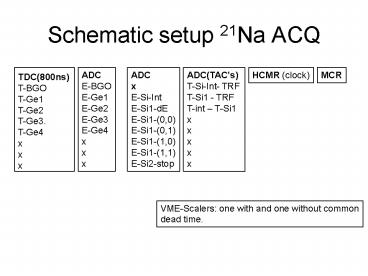
Title: Schematic setup 21Na ACQ
1
Schematic setup 21Na ACQ
ADC E-BGO E-Ge1 E-Ge2 E-Ge3 E-Ge4 x x x
TDC(800ns) T-BGO T-Ge1 T-Ge2 T-Ge3. T-Ge4 x x x
HCMR (clock)
MCR
ADC x E-Si-Int E-Si1-dE E-Si1-(0,0) E-Si1-(0,1) E-
Si1-(1,0) E-Si1-(1,1) E-Si2-stop
ADC(TACs) T-Si-Int- TRF T-Si1 - TRF T-int
T-Si1 x x x x x
VME-Scalers one with and one without common dead
time.
2
scaler
TFA
CFD
TDC1 BGO Ge1 Ge4
Fixed delay
ADC2 BGO Ge1 Ge4
MA
stretcher
4x
PA
Ge1
MA
Ge2
Ge3
TFA
CFD
or
Ge4
Shield
Ge trigger and scalers
Ge1
Ge2
Ge3
Reserve Not used(?)
Ge4
Analogue time signals Ge
3
TAC start stop
CFD
RF
ADC3
Si-int plane
PA
TFA
CFD
TAC start stop
MA
Si-dE Si1 (300 um) Focal pl
PA
TAC start stop
TFA
CFD
MA
ADC1
Amp/Shp ch0 ch1 ch2 ch3
4-Pos
Si-stop Si2 (150 um) Focal pl
PA
Si2 trigger
CFD
TFA
MA
Analogue time signals Si
4
dead time measurement
dual timer
start noto out
VME scaler 1
MCR 2 dead time (TM) coinc
win (FC) 4
fi/fo
T-int
start noto out
T-Si1
VME scaler 2
fi/fo
T-Si2
or Ge
HCMR OPA1 out
to cyclo beam off
trigger logic
Recommended
