
CHAPTER 18 Direct Current (DC) Circuits PowerPoint PPT Presentation
1 / 24
Title: CHAPTER 18 Direct Current (DC) Circuits
1
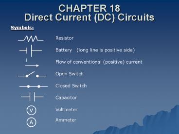
CHAPTER 18Direct Current (DC) Circuits
Symbols
Resistor
Battery (long line is positive side)
Flow of conventional (positive) current
Open Switch
Closed Switch
Capacitor
Voltmeter
V
Ammeter
A
2
Resistors in Series
The same amount of current flows thru each
resistor.
RT Req R1 R2 when resistors are in series
Circuit Analysis Find the voltage at every point
(a, b, and c) in Fig 18.2 if the battery is 12V
and R1 and R2 are 2.0 and 4.0 ohm
respectively. Strategy Usually 1. Find total
resistance (RT) 2. Use total resistance to
find total current (IT) 3. Use IT and
individual resistance to calculate various ?Vs.
3
- Find total resistance (RT)
- 2. Use total resistance to find total current
(IT) - 3. Use IT and individual resistance to calculate
various ?Vs.
RT 2.0 ? 4.0 ? 6.0 ? (RT R1 R2) I
12 Volt/6.0 ? 2.0 Amp (A) (V I R) V at
battery discharge ( end) 12 V ?V across
resistors IR ?V1 2.0 A x 2.0 ? 4.0 V ?V2
2.0 A x 4.0 ? 8.0 V
Va 12 V
Vc 0 V (8V-8V)
Vb 8 V (12V-4V)
4
Series Circuit
RT R1 R2
IT I1 I2
?V I R
?VT ?V1 ?V2
5
Resistors in Parallel
Total current splits and flows partially thru
each resistor before recombining.
IT I1 I2
?VT ?V1 ?V2
?V I R
6
Circuit Analysis Find the current flowing through
each resistor in Fig 18.4 if the battery is 12V
and R1 and R2 are 2.0 and 4.0ohm respectively.
RT 1.3 ?
V I R
?V1 12 Volts I1 x R1 12 V I1 x 2.0?
IT I1 I2 9.0A
I1 6.0 A
?V2 12 Volts I2 x R2 12 V I2 x 4.0?
VT IT x RT VT 9.0A x 1.3?
I2 3.0 A
VT 12V
7
Combination Circuits
Reading the Circuit Diagram The 4.0? resistor is
in series with the 8.0? resistor in front of it
because all of the current that passes through
the 8.0? resistor must also pass through the 4.0?
resistor. The 6.0? resistor is not in series
with the 4.0? resistor because all the current
passing through the 4.0? resistor does not pass
through the 6.0? resistor. Some of it passes
through the 3.0? resistor. The 6.0? resistor and
the 3.0? resistor are in parallel because all the
current entering point b passes through point c.
8
Combination Circuit Examples
Calculate Total Resistance
P18.6
- Trace Current Flow
- 18?, 9.0?, 6.0? parallel
RC 3.0?
- Combo 3.0? in series with 12?
- RT 12? 3.0? 15?
IT 2.0A
P18.7
- Trace current flow a to b
- 2 resistors in parallel
RC .5R?
- Horizontal R,R, and RC are in series
RT 2.5R?
- Vertical R is immaterial
P18.8
- Trace current flow
- Two 5.0? in series
RC1 10.0?
- RC1 in parallel with vertical 5.0?
RC2 3.3?
- Horizontal 5.0?, RC2 and horizontal 1.5? are in
series
RT 9.8?
9
Test Yourself
Working from top right of circuit
RP1
3.0 ?
RS1
6.0 ?
RP2
3.0 ?
RS2
5.0 ?
RPC
2.7 ?
RT
5.7 ?
10
Quiz Yourself
RP1 3.3 ? RS1 7.3 ? RP2 2.1 ? RT 5.1 ?
11
Real Batteries
- emf electromotive force (not a true force)
- 12 volts in a 12Volt battery
- gross voltage
- All batteries have internal resistance
(especially as they grow old) - r internal resistance
- Voltage drop within the battery is Ir
- ?V Terminal Voltage (net voltage) ? - Ir
- Terminal Voltage is measured at the terminals of
the battery with current flowing.
12
Example Problem (Circuit Analysis) Find a) the
power dissipated across each resistor, b) the
current through each resistor, and c) the voltage
between all the resistors.
Strategy Find the total resistance and then the
total current. RT 3.9? IT 3.1A
Trace the circuit starting with the positive side
of the battery and determine V at exit of each
resistor (V-?V) VB 12.0V V2? 5.8V
(12.0-2.0x3.1) V4? V6? V10? 0 Volts all
directly connected to negative terminal of
battery
13
With all current and resistance known, calculate
power dissipation.
PT (3.1A)2 (3.9?) 37.5 Watts
14
Complex DC Circuits
- Kirchhoffs Rules for Complex Circuits
- Junction Rule Sum of currents entering a
junction equal sum of currents leaving junction - Loop Rule Sum of the ?Vs in a loop must
equal zero - Apply Rules
- Use rules to set up as many equations as you have
unknowns. - Solve equations simultaneously for unknowns.
NOTE Make best guess regarding current
direction. If current calculates to be negative,
you merely guessed the wrong direction.
15
I1 I2 I3
2.0A -3.0A -1.0A
Not required for AP Exam
Upper loop (counterclockwise starting with
battery)
14V 4.0I2 10V 6.0I1 0
Overall loop (counterclockwise starting with
battery)
14V 4.0I2 2.0I3 0
Junction
I1 I2 I3
16
Required for AP Exam
Analyze the single loop to find I using
Kirchhoffs Rule(s).
Guess direction of current
Clockwise
Use Loop Rule (starting with 18V battery)
?V 0 18V 6.6I 12V 2.0I 1.0I
?V 0 6V 9.6I
I .63 A
17
Capacitors in Circuits
A capacitor in an uncharged state gains a fixed
amount of charge when the circuit is closed. Once
it has the fixed amount of charge the flow of
current in the circuit ceases.
18
Combination of Capacitors in DC Circuits
Parallel Capacitors
In parallel ?V1 ?V2 ?VT just like the voltage
drop across resistors in parallel.
Total charge is sum of individuals
QT Q1 Q2
Q1 C1?V1 C1?VT Q2 C2?V2 C2?VT QT C1?VT
C2?VT CT?VT C1?VT C2?VT
CT C1 C2
Unlike resistors in parallel Like resistors in
series
NOTE Book uses Ceq instead of CT.
19
Series Capacitors
For capacitors in series, the magnitude of the
charge on each plate must be identical. Why?
Q1 Q1-
No net charge on a capacitor
Q1- Q2
positive charge moved from C1 to C2 making the
right plate on C1negative and the left plate on
C2 positive. What really happened?
Q2 Q2-
No net charge on a capacitor.
20
Q1 Q2 QT
QT CTVT
?V1 ?V2 ?VT
Unlike resistors in series Like resistors in
parallel
NOTE Book uses Ceq instead of CT
21
Capacitors can act as surge protectors.
22
Analyzing Circuits Immediately After Closing a
Switch and at Steady State
Immediately After Closing Switch I1 I2
0 Amps
No resistance in the path to the capacitor so all
charge flows that direction
? Amps
At Steady State I1 I2
The capacitor acts as an infinite resistance
device with no flow through it.
?V/R Amps
0 Amps
23
Example Problem (Steady State)
Calculate the charge, Q1, stored on the capacitor
at steady state.
- Strategy
- At steady state there is no flow of current
- either to or from the capacitor.
- 2. Analyze the circuit as if the capacitor were
not - even in the circuit.
- ?V across 20? resistor equal ?V across the
- capacitor.
- 4. Chose the appropriate formula to calculate Q.
Solution RT 30? IT 1.0A ?V20? 20V
Q (20x10-6F)(20V)
Q 400x10-6 C
24
Ratio of Charges in Parallel Capacitors
Q1 C1?V1 C1?V Q2 C2?V2 C2?V
Ratios of Charges in Series Capacitors
Q1 C1?V1 Q Q2 C2?V2 Q ?V1
Q/C1 ?V2 Q/C2
Recommended
