
TR6850???? PowerPoint PPT Presentation
Title: TR6850????
1
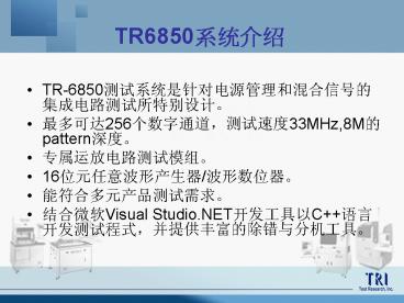
TR6850????
- TR-6850?????????????????????????????
- ????256?????,????33MHz,8M?pattern???
- ???????????
- 16?????????/??????
- ????????????
- ????Visual Studio.NET?????C????????,????????????
??
2
System Architecture
- Up to 8-Site Parallel Testing
- Cable Out
- Maximum 256 Logic I/O Channels
- High Precision Measurement Unit
- Arbitrary Waveform Generator
- Digitizer
- Low Cost Mixed Signal Tester
3
System Architecture
- Test Head Architecture
PC Interface
Digital Module
Analog Module
4
Targeted Applications
- For Digital, Analog and Mixed Signal Device
- MCU , Interface / Driver Digital Chip
- AD Converter , DA converter
- Voltage Comparator
- Operational Amplifier
- Regulator Shunt/Voltage Regulator, LDO
5
Targeted Applications
- Hall Sensor
- PWM Switching , PWM Controller
- Power Factor Control IC
- DC to DC converter
- Detector, Voltage Detection
- MOSFET
- - - - -
6
Electrical Specifications
- AC64/AC32 64 /32I/O Channels Board
- Pin Configuration( I/O Channel) 64 /32pins
- Parametric Measurement Unit 4 Sets (
8-pin share) - Pin Level Source Per
pin level set - Driver Voltage Range -2.0V
to 8V - Comparator Voltage Range -2.0V to 8V
- Min. Pulse Width
10ns - Micro Instruction CALL,
MATCH,MPAT,MLEN
RPT,LOOP,LPEND,STOP,TS
7
Electrical Specifications
- AC64/32 64/32 I/O Channels Board continue
- Min. Period 30ns 40ms
- Period resolution 10ns
- Data Rate 33MHz
- Timing Generators 4 edge / Pin
- Timing Set 16 change on the fly
- Edge Placement resolution 2.5ns
- Time Measurement Resolution 10ns
8
Electrical Specifications
- AC64/32 64/32 I/O Channels Board continue
- Drive Mode
0,1,NF,NRZ,RZ,RO,SBC - IO Mode 0,1,NF
- Strobe Mode Edge/Window
- Pattern Memory Depth 4M8M
- Fail Memory Depth 4K
- Pattern Symbol 0/1//X/Z/L/H
9
Electrical Specifications
- OVC -- Octal V/I Resource Board
- Voltage Force and Measure Range20V ,16V,8V,4V,2V
- Voltage Force and Measure Resolution16 bits
- Voltage Force and Measure Accuracy
- 2V (0.01 of value0.05 of range )
- 4V (0.01 of value0.05 of range )
- 8V (0.01 of value0.05 of range )
- 16V (0.01 of value0.05 of range )
- 20V (0.01 of value0.05 of range )
- Voltage clamp Resolution16 bits
- Current Force and Measure Range1uA,10uA,100uA,1mA
, 10mA,100mA,200mA - Current Force and Measure Resolution16 bits
10
Electrical Specifications
- OVC -- Octal V/I Resource continue
- Current Force and Measure Accuracy
- 1uA (0.2 of value0.2 of range )
- 10uA (0.1 of value0.1 of range )
- 100uA (0.1 of value0.1 of range )
- 1mA (0.1 of value0.1 of range )
- 10mA (0.1 of value0.1 of range )
- 100mA (0.1 of value0.1 of range )
- 200mA (0.1 of value0.1 of range )
- Current Clamp Resolution16 bits
- 10KSPS DDS programmable to any Channel(16 bit)
- 10KSPS Digitizer multiplexed to two channels(16
bits) - DVM Differential voltage measure between two
channels
11
Electrical Specifications
- PVC -- Pulse Mode V/I Resource
- 2 Independent V/I Resource
- Floating Ground,Pulse Mode
- Programmable Pulse period
- Protection Timer
- Voltage Force and Measure Range4V,8V,16V,32V,46V
- Voltage Force and Measure Resolution16 bits
- Voltage Force and Measure Accuracy
- 8V (0.3 of value0.15 of range )
- 16V (0.3 of value0.15 of range )
- 32V (0.3 of value0.15 of range )
- 46V (0.3 of value0.21 of range )
12
Electrical Specifications
- PVC -- Pulse Mode V/I Resource continue
- Current Force and Measure Resolution16 bits
- Current Force and Measure Accuracy
- 150mA ( 0.5 of value0.25 of range )
- 300mA ( 0.5 of value0.25 of range )
- 1.5A ( 0.5 of value0.25 of range )
- 3A ( 0.5 of value0.25 of range
) - 5A ( 0.5 of value0.25 of range
) - 10A ( 0.5 of value0.25 of range )
- 15A ( 1.0 of value0.25 of range )
- 30A ( 1.0 of value0.25 of range )
13
Electrical Specifications
- DVC -- Full Four-Quadrant V/I Source
- Voltage Force and Measure Range1V, 2V, 4V,
- 8V,16V, 32V, 48V
- Voltage Force and Measure Resolution16 bits
- Voltage Force Accuracy (0.05 of value0.05
of range) - Voltage Measure Accuracy (0.03 of value 0.03
of range) - Current Force and Measure Range2uA,20uA,200uA,
2mA,200mA, 1A, 2A
14
Electrical Specifications
- DVC -- Full Four-Quadrant V/I Source continue
- Current Force and Measure Resolution16 bits
- Current Force and Measure Accuracy
- 2uA 200uA (0.05 of value0.05 of range
10nA ) - 2mA 200mA (0.1 of value0.1 of range)
- 1A2A (0.3 of value0.1 of range)
- Differential voltage measure between two channels
- Measure Resolution 16 bit
- Measure accuracy (0.2 of range 200uV)
- 20mV, 100mV, 200mV, 1V, 2V, 4V, 10V, 20 , 100V
15
Electrical Specifications
- Arbitrary Waveform Generator continue
- Pin Counts Per Module2
- 4 Single-ended or 2 Differential.
- Resolution16 Bits.
- Sampling Rate40M SPS max,625k SPS min
- Waveform Memory4M.
- Output Range5Vpp_at_50 ohm load
- 10Vpp_at_ a high-impedance load
- Accuracy 0.1dB
- DC Offset Range2.5V_at_50 ohm load
- Accuracy 5mV
16
Electrical Specifications
- Arbitrary Waveform Generator - continue
- Harmonic products ans spurs 75 dBc
- Output Impedance50 ohm,75 ohm.
- FilterAnalog, 2MHz, 500kHz, 50kHz, 5k, Through.
- TTL Rising edge PW40ns min.
- SYNC OutputTTL Duty Cycle20 to 80.
- Marker OutputTTL 8 Sample clock periods.
- Frequency Range1Hz 1MHz
17
Electrical Specifications
- Digitizer
- Input -3dB Freq. 1Mhz
- 16bits (Low Speed 500Ksps)/ 14bits (High Speed
10Msps) - 4 single or 4 differential-end channels Output
10Vpp _at_ 50 ohm Load to GND - MEM Depth 4M16bits/channel
- Anti-Filter 20kHz, 200kHz, 2Mhz
- Notch Filter Notch freq. 1Khz for audio
testing. - Digital Filter 2x, 4x, 8x, 16x, 32x, 64x
decimation filter. - User Offset 2.0V
- Input Impedance 50ohm, 1Mhz common ground or
100ohm, 10kohm differential. -
18
Electrical Specifications
- Digitizer - continue
- PGA ranges
- Single ended 0.1, 0.5, 1, 2, 5, 10
- Differential 0.05, 0.1, 0.25, 0.5, 1,
2.5, 5 - Dynamic Performance (1kHz -1dBFS test tone with
2x decimation filter) - THD lt -80dBc
- SNR gt 80dBc
- THDN lt -80dBc
- Dynamic Performance (1kHz -1dBFS test tone with
Notch filter) - THD -105dBc
- SNR 99dBc
- THDN -98dBc
-
19
Electrical Specifications
- TMU -- Time Measure Unit
- Positive/Negative Slope.
- Counter,Time measurement,Rising/Failing time.
- Time Resolution625ps Propagation delay
- Timeout function and Overflow state.
- Input waveformSine,square,sawtooth.
- Low Impedance Inputs A, B
- 10V RangeImpedance 2K/1M Ohm Nominal
- 2.5V Range Impedance 2K/1M Ohm Nominal
- Input Threshold Accuracy0.5 of Range
20
Electrical Specifications
- OP-LOOP Board
- Four OP AMP Loop
- DC Measurement16 bits
- Common Mode DAC16 bits
- AC Stimulus16 bits High Speed DAC
- AC measurement12 bit ADC,10MHz Sample Rate
- Loop Reference DAC16 bits
- Input Offset voltage (Vos)
- Input Offset Current (Ios)
- Open loop gain (Avol)
21
Electrical Specifications
- OP-LOOP Board -- continue
- Command Mode Rejection Ration (CMRR)
- Power Supply Rejection Ration (PSRR)
- Gain Bandwidth Product (GBW)
- Slew Rate (SR)
22
Electrical Specifications
- KVS board
- 2 Channels Floating Ground System
- 16bit ADC for voltage and current measure
- 16 bit DAC for voltage and current force
- Vmax 900V
- Imax 15mA
- Vrange 100V, 200V, 500V,1000V accuracy
(0.05 of value 0.25 of range) - Irange 15uA, 150uA, 1.5mA, 15mA accuracy(0.05
of value 0.35 of range) - Time Max 10 sec
23
Electrical Specifications
- QVC board
- Four Independent, Full Four-Quadrant VIs
- Voltage to 45V, Current to 1A
- Voltage ranges 1, 2, 4, 8, 16, 32, 45 vlots
- Current ranges 2uA, 20uA, 200uA, 2mA, 20mA,
200mA, 1A - 16 bits force and measure resolution
- Measure V without forcing
24
Electrical Specifications
- QVC board
- Voltage Force
- Forcing Resolution 16bits
- Force Accuracy (0.05 of value 0.05 of range)
- Voltage Measure
- Measure Resolution 16bits
- Measure Accuracy (0.05 of value 0.05 of
range)
25
Electrical Specifications
- QVC board
- Current Force
- Forcing Resolution 16bits
- 2uA Range Accuracy (0.1 of value 0.1 of
range 10nA) - 20uA 1A Range Accuracy (0.1 of value 0.1
of range) - Current Measure
- Measure Resolution 16bits
- 2uA Range Accuracy (0.1 of value 0.1 of
range 10nA) - 20uA 1A Range Accuracy (0.1 of value 0.1
of range)
26
Electrical Specifications
- MVC board
- Full Four-Quadrant V/I Channel2
- Max. Voltage100V -45V
- Max. Current 500mA / 45VRange,100V_at_200mA
- Voltage Ranges100V, 50V, 32V, 16V,8V,4V
- Voltage Force Accuracy (0.05 of value0.1 of
range) - Voltage Measure Accuracy (0.05 of Value 0.1
of range)
27
Electrical Specifications
- MVC board -continue
- Voltage Clamp Resolution16 bit
- Current Range2uA, 20uA, 200uA, 2mA, 20mA, 200mA,
500mA - Current Force Accuracy
- 2uA 200uA (0.1 of value0.2 of range
10nA ) - 2mA 200mA (0.1 of value0.2 of range)
- 500mA (0.1 of value0.2 of
range) - Current Measure Accuracy
- 2uA 200uA (0.1 of value0.2 of range
10nA ) - 2mA 200mA (0.1 of value0.2 of range)
- 500mA (0.1 of value0.2 of
range) - Current Clamp Resoulation16 bit
28
Electrical Specifications
- MFB ( 8 channel )
- Ramp force accuracy
- 4V Range 1mV
- 12V Range 2.5mV
- Measure accuracy
- 4V range none filter 1mV
- 10 range none filter 2.5mV
- 4V range with filter 2.5mV
- 10 range with filter 5mV
- AWG sample rate 1MHZ _at_ 64K length
- Digitizer Sample rate 250K _at_ 64K length
- AWG Digitizer loop back testing 1KHZ _at_3V gt
70dB - SDIO function Sample Rate 1Mbps
- A,B, C,D,E,F,G,H combination for data,
clk signal.
Recommended
