
TeamMembers PowerPoint PPT Presentation
1 / 63
Title: TeamMembers
1
TeamMembers
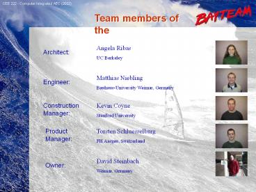
Team members of the
Team members of the
Angela Ribas
Architect
UC Berkeley
Matthias Niebling
Engineer
Bauhaus-University Weimar, Germany
Construction Manager
Kevin Coyne
Stanford University
Product Manager
Torsten Schluesselburg
FH Aargau, Switzerland
David Steinbach
Owner
Weimar, Germany
2
Location
CAMPUS LOCATION
CAMPUS LOCATION
- BAY AREA / CITY OF SAN FRANCISCO
- UNIVERSITY OF SAN FRANCISCO
- MAIN CAMPUS AT FULTON STREET
3
CAMPUS VIEW
CAMPUS VIEW
N
Map
4
SURROUNDING BUILDINGS
SURROUNDING BUILDINGS
SITE MAP
Textures
5
SITE
N
PANORAMIC VIEW
- FLAT GROUND
- FACING FULTON STREET
SITE MAP
Building location
6
A_First concept
FIRST ARCHITECTURAL CONCEPT
FOREST
AN OPEN AND FRIENDLY SPACE WHERE PEOPLE CAN
INTERACT
CORE VIEW
Concept
7
FIRST ARCHITECTURAL CONCEPT
FIRST FLOOR PLAN
Plan
8
FIRST ARCHITECTURAL CONCEPT
BASEMENT
Plan
9
FIRST ARCHITECTURAL CONCEPT
SECOND FLOOR
Plan
10
FIRST ARCHITECTURAL CONCEPT
THIRD FLOOR
Plan
11
FIRST ARCHITECTURAL CONCEPT
N
C
B
B
A
A
C
SECTION AA
Sections
SECTION CC
SECTION BB
12
FIRST ARCHITECTURAL CONCEPT
N
SOUTH FACADE
SOUTH FACADE
NORTH FACADE
NORTH FACADE
EAST FACADE
TOP VIEW
Elevations
WEST FACADE
13
A1_E_SOLUTION1
CEE 222 - Computer Integrated AEC (2002)
STRUCTURAL SYSTEM
STRUCTURAL SYSTEM
14
Loading assumptions
CEE 222 - Computer Integrated AEC (2002)
STRUCTURAL SYSTEM
STRUCTURAL SYSTEM
DEAD LOADS
LIVE LOADS
LATERAL LOADS
Load Assumptions
15
Concrete Walls
CEE 222 - Computer Integrated AEC (2002)
STRUCTURAL SYSTEM
STRUCTURAL SYSTEM
Typical element sizes
Concrete walls 12
Structural elements
16
Girders
CEE 222 - Computer Integrated AEC (2002)
STRUCTURAL SYSTEM
STRUCTURAL SYSTEM
Structural elements
17
2 former Solutions
CEE 222 - Computer Integrated AEC (2002)
STRUCTURAL SYSTEM
STRUCTURAL SYSTEM
- Composite floor deck
- Bays of 30 x 30 ft
- Advantage only 4 columns needed
- Steel Frame Structure
- Spans of 15 ft (concrete elements) and
- 30 ft (steel frames)
- Advantage slab can be thin (reduction of dead
loads)
Former solutions
18
Typical element sizes
CEE 222 - Computer Integrated AEC (2002)
STRUCTURAL SYSTEM
STRUCTURAL SYSTEM
Most economic compromise
takes the advantages of both structural solutions
Typical element sizes
- Concrete walls 12
- Slab Composite floor deck, total height 4 ¾
- Secondary beams 8 (HEA 200)
Typical element sizes
19
Gravity Load Path1
CEE 222 - Computer Integrated AEC (2002)
STRUCTURAL SYSTEM
STRUCTURAL SYSTEM
Gravity Load Path1
20
Gravity Load Path2
CEE 222 - Computer Integrated AEC (2002)
STRUCTURAL SYSTEM
STRUCTURAL SYSTEM
21
Gravity Load Path3
CEE 222 - Computer Integrated AEC (2002)
STRUCTURAL SYSTEM
STRUCTURAL SYSTEM
22
Gravity Load Path4
CEE 222 - Computer Integrated AEC (2002)
STRUCTURAL SYSTEM
STRUCTURAL SYSTEM
23
Gravity Load Path5
CEE 222 - Computer Integrated AEC (2002)
STRUCTURAL SYSTEM
STRUCTURAL SYSTEM
24
Foundation MainBuilding
CEE 222 - Computer Integrated AEC (2002)
STRUCTURAL SYSTEM
STRUCTURAL SYSTEM
Foundation will be
- a ground plate with a height of 15
- at the positions of concentrated loads
(columns) strengthening of the ground plate up
to 24
Foundation Main Building
25
Foundation Auditoroium
CEE 222 - Computer Integrated AEC (2002)
STRUCTURAL SYSTEM
STRUCTURAL SYSTEM
Foundation will be
- a ground plate with a height of 15
- at the positions of concentrated loads
(columns) strengthening of the ground plate up
to 24
- the floor of the auditorium is declined.
- using a stepping instead of declination -gt
horizontal loads (out of gravity loads) are
avoided
Foundation - Auditorium
26
Lateral Load Path Left
CEE 222 - Computer Integrated AEC (2002)
STRUCTURAL SYSTEM
STRUCTURAL SYSTEM
Symmetrical plan
- no additional moment occurs
27
Lateral Load Path Right
CEE 222 - Computer Integrated AEC (2002)
STRUCTURAL SYSTEM
STRUCTURAL SYSTEM
Asymmetrical plan
- additional moment
(MNe)
28
Outside Wall
CEE 222 - Computer Integrated AEC (2002)
STRUCTURAL SYSTEM
STRUCTURAL SYSTEM
Outside concrete walls
- do not act as a slab because of number of
openings
- high amount of reinforcement is needed
29
A1_C_Slide1
CONSTRUCTION SITE PLAN
CONSTRUCTION SITE PLAN
Existing Buildings
Site Access (Fulton)
Project Office
Material Laydown Storage
Crane
Building Perimeter
Site Perimeter
Site plan
30
A1_C_Slide2
CONCEPT 1 CONSTRUCTION
CONCEPT 1 CONSTRUCTION
- EXCAVATION
- 18 Hard Strata Excavation No retaining wall
necessary - FOUNDATION
- Poured Reinforced Concrete Mat Slab w/ Column
Footings - SUPERSTRUCTURE A
- Reinforced Concrete Moment Frame
- Cast-in-Place Reinforced Concrete Shear Walls
- Cast-in-Place Composite Concrete/Steel Floor
System
- SUPERSTRUCTURE B
- Steel Moment Frame
- Cast-in-Place Composite Concrete/Steel Floor
System - EXTERIOR FACADE
- Concrete and Glass Curtain Wall System
Materials and Methods
31
A1_C_Slide3
CONCEPT 1 COST
CONCEPT 1 COST
Structural Solution 1
Structural Solution 2
- Concrete Moment Frame
- Concrete Shear Walls
- Steel Moment Frame
- Concrete Shear Walls
Total Cost 6,070,122 Per S.F.
164.06
Total Cost 5,892,664 Per S.F.
159.26
32
A1_C_Slide2
CONCEPT 1 SCHEDULE
CONCEPT 1 SCHEDULE
Schedule Duration 9 months
Start 9/20/2015 End 7/7/2016
Schedule Duration 9 months
Start 9/20/2015 End 7/7/2016
MILESTONE 1 3/01/16 Foundation Complete
MILESTONE 2 5/10/16 Shell Complete MILESTONE
3 9/30/16 Move-In
Conceptual Schedules
33
A_Second concept
SECOND ARCHITECTURAL CONCEPT
SECOND ARCHITECTURAL CONCEPT
CONCEPTUAL IDEAS
Progress
34
SECOND ARCHITECTURAL CONCEPT
PLAZA
A PLAZA SURROUNDED BY WATER
Concept
35
SECOND ARCHITECTURAL CONCEPT
FIRST FLOOR PLAN
Plan
36
SECOND ARCHITECTURAL CONCEPT
BASEMENT PLAN
Plan
37
SECOND ARCHITECTURAL CONCEPT
SECOND FLOOR PLAN
Plan
38
SECOND ARCHITECTURAL CONCEPT
THIRD FLOOR PLAN
Plan
39
SECOND ARCHITECTURAL CONCEPT
N
A
A
S / N FACADE
SECTION AA
E / W FACADE
SOUTH / NORTH FACADE
EAST / WEST FACADE
TOP VIEW
Section / Elevations
40
A2_E_SOLUTION1
CEE 222 - Computer Integrated AEC (2002)
STRUCTURAL SYSTEM 1
STRUCTURAL SYSTEM 1
41
Constraints
CEE 222 - Computer Integrated AEC (2002)
STRUCTURAL SYSTEM 1
STRUCTURAL SYSTEM 1
Solution 1
- the whole building is based on 4 large columns
at the corners
- an additional 4 columns in the core
42
Gravital Structure
CEE 222 - Computer Integrated AEC (2002)
STRUCTURAL SYSTEM 1
STRUCTURAL SYSTEM 1
In each slab there will be 4 large girders
- to collect gravity loads and transport them to
the
framework and the core columns
Gravity Structure
43
Framework
CEE 222 - Computer Integrated AEC (2002)
STRUCTURAL SYSTEM 1
STRUCTURAL SYSTEM 1
Realizing the large span by a huge framework
- to collect gravity loads and transport lateral
loads
- to reduce deformation of the slabs
Gravity Structure
44
Element sizes
CEE 222 - Computer Integrated AEC (2002)
STRUCTURAL SYSTEM 1
STRUCTURAL SYSTEM 1
Framework
Typical Element sizes
- Slab Composite floor deck, total height 4 ¾
(Span 11ft)
- Secondary beams 8 (HEA 200)
- Core Columns 20 x 20
- Outside Columns 40 x 40 (Assumption)
Typical element sizes
45
GravityLoadPath
CEE 222 - Computer Integrated AEC (2002)
STRUCTURAL SYSTEM 1
STRUCTURAL SYSTEM 1
Forces are transported
- from secondary beams to the girders
- from girders to the outside framework and the
inner core
- by vertical elements into the ground
46
Lateral Structure
CEE 222 - Computer Integrated AEC (2002)
STRUCTURAL SYSTEM 1
STRUCTURAL SYSTEM 1
Stiffening the inside of the box by EBFs
(eccentric braced frames)
- Advantage in case of an earthquake, EBFs can
absorb some of energy
Lateral Resisting Structure
47
LateralLoadPath_Left
CEE 222 - Computer Integrated AEC (2002)
STRUCTURAL SYSTEM 1
STRUCTURAL SYSTEM 1
Symmetrical plan
- no additional moments occur
48
LateralLoadPath_Top
CEE 222 - Computer Integrated AEC (2002)
STRUCTURAL SYSTEM 1
STRUCTURAL SYSTEM 1
Symmetrical plan
- no additional moments occur
49
Foundation Columns
CEE 222 - Computer Integrated AEC (2002)
STRUCTURAL SYSTEM 1
STRUCTURAL SYSTEM 1
Foundation of the columns is critical because of
seismic issues
- the outside columns must be able to rock -gt base
isolation system
Foundation
50
FoundationBasement
CEE 222 - Computer Integrated AEC (2002)
STRUCTURAL SYSTEM 1
STRUCTURAL SYSTEM 1
Foundation of the basement
- will be a ground plate
- in the core, a strengthening of the ground plate
becomes necessary (columns)
Foundation
51
A2_E_SOLUTION2
CEE 222 - Computer Integrated AEC (2002)
STRUCTURAL SYSTEM 2
STRUCTURAL SYSTEM 2
Solution 2
- additional columns are used to reduce the span
- the building becomes more economical
52
InsideElements
CEE 222 - Computer Integrated AEC (2002)
STRUCTURAL SYSTEM 2
STRUCTURAL SYSTEM 2
Stiffening inside of the box by EBFs (eccentric
braced frames)
Lateral Resisting Structure
53
OutsideElements
CEE 222 - Computer Integrated AEC (2002)
STRUCTURAL SYSTEM 2
STRUCTURAL SYSTEM 2
Stiffening also the outside of the box by EBFs
- with this structural solution there are shorter
spans of about 30 ft.
- EBFs can absorb energy in case of an earthquake
- Columns are not stressed with the entire
earthquake energy
Lateral Resisting Structure
54
LoadPaths and Foundation
CEE 222 - Computer Integrated AEC (2002)
STRUCTURAL SYSTEM 2
STRUCTURAL SYSTEM 2
Load paths and foundation are similar to the
first structural solution
55
A2_C_Slide1
CONCEPT 2 CONSTRUCTION
CONCEPT 2 CONSTRUCTION
A1_C_Slide2
- EXCAVATION
- 18 Hard Strata Excavation No retaining wall
necessary - FOUNDATION A
- Concrete Slab and Base Isolation System
- FOUNDATION B
- Poured Reinforced Concrete Mat Slab w/ Column
Footings - SUPERSTRUCTURE A
- Exterior Steel Truss System
- Interior Steel Eccentrically Braced Frame (EBF)
System
- Cast-in-Place Composite Concrete/Steel Floor
System - SUPERSTRUCTURE B
- Exterior/Interior Steel EBF System
- Cast-in-Place Composite Concrete/Steel Floor
System - EXTERIOR FACADE
- Concrete and Glass Curtain Wall System
Materials and Methods
56
A2_C_Slide2
CONCEPT 2 COST
CONCEPT 2 COST
A1_C_Slide3
Structural Solution 1
Structural Solution 2
- Steel Truss/EBF system
- Base Isolation System
- Exterior/Interior EBF system
Total Cost 6,804,132 Per S.F.
183.90
Total Cost 5,977,581 Per S.F.
161.56
57
A1_C_Slide2
CONCEPT 2 SCHEDULE
CONCEPT 2 SCHEDULE
Schedule Duration 9.5 months
Start 9/20/2015 End 7/17/2016
Schedule Duration 8 months
Start 9/20/2015 End 5/21/2016
MILESTONE 1 3/29/16 Foundation Complete
MILESTONE 2 6/21/16 Shell Complete MILESTONE
3 9/30/16 Move-In
Conceptual Schedules
58
Decision_Forest
CEE 222 - Computer Integrated AEC (2002)
DECISION MATRIX
DECISION MATRIX
PROS
A
- Daylight / Green area inside
- No extended footprint
- Owners preference
- Large glass facade
E
- Interesting retractable roof
- Steel is efficient and cost effective
C
- Straightforward construction sequencing
CONS
Costs
5.9 Mil
- More conventional design
A
- Only one main access
E
- Relatively simple box - structure
C
- Retractable roof / Glass facade costly
FOREST
59
Decision_Plaza
CEE 222 - Computer Integrated AEC (2002)
DECISION MATRIX
DECISION MATRIX
PROS
- Open ground floor
A
- More unusual design
- Two accesses
- Daylight inside
E
- Interesting structure (large spans)
- A lot of details must be solved
C
- EBF system is cost and
schedule efficient
CONS
Costs
6.8 Mil
- Extended footprint
A
- Space on first floor wasted
E
- Again interesting structure with A LOT of details
C
- Base Isolation System costly
PLAZA
60
Matrix
CEE 222 - Computer Integrated AEC (2002)
DECISION MATRIX
DECISION MATRIX
Costs
5.9 Mil
6.8 Mil
- Daylight / Green area inside
PROS
- Open ground floor
- No extended footprint
- More unusual design
- Owners preference
- Two accesses
- Daylight inside
- Large glass facade
- Interesting retractable roof
- Interesting structure (large spans)
- A lot of details must be solved
- Steel is efficient and cost
- EBF system is cost and
effective.
schedule efficient
- Straightforward construction
sequencing
- More conventional design
- Extended footprint
CONS
- Only one main access
- Space on first floor wasted
- Relatively simple box - structure
- Again interesting structure
with a lot of details
- Retractable roof/Glass facade
- Base Isolation System costly
costly
Comparison
61
Lessons Learned
CEE 222 - Computer Integrated AEC (2002)
LESSONS LEARNED
LESSONS LEARNED
New media needs further development to work
properly every time
- We encountered problems, especially in using
Netmeeting
The phone line we have as backup is used every
time in present meetings
- The data archival is very important but also
complicated
Necessity of keeping track of the different
versions of a document
Developing a tool to easily gather and manage data
62
Further Collaboration
CEE 222 - Computer Integrated AEC (2002)
FURTHER COLLABORATION
FURTHER COLLABORATION
The discussion forum should be used more often
We used it at the beginning of the project quite
often but recently we fell back to Emails
We should announce team-meetings (with all the
members) once a week
Discussing with everybody (other disciplines)
brings an improved learning experience
The notification mechanism should be improved
Importance of knowing if an email, attachment
arrived and was useful
63
Questions?
Thank you
Thank you
QUESTIONS ?
Recommended
