
Liquid Argon Time Projection Chamber: Purity and Purity Monitoring - PowerPoint PPT Presentation
1 / 1
Title:
Liquid Argon Time Projection Chamber: Purity and Purity Monitoring
Description:
Title: Liquid Argon Time Projection Chamber: Purity and Purity Monitoring Author: David Gerstle Last modified by: David Gerstle Created Date: 5/13/2006 2:12:49 PM – PowerPoint PPT presentation
Number of Views:32
Avg rating:3.0/5.0
Title: Liquid Argon Time Projection Chamber: Purity and Purity Monitoring
1
Liquid Argon Time Projection Chamber Purity and
Purity Monitoring
Why Build It?
LARGE Issues to be Addressed
Achieving Purity FNAL PAB set-up
- We are building a filtering device (left) at the
Proton Assembly Building (PAB). - The LAr must be pure to 0.03 ppb (for a 3m drift)
O2 to prevent the absorption of ionization
electrons as they drift toward the readout
planes. - To achieve this, we are developing LAr
filtration system employing dually a Trigon
oxygen filter and a molecular sieve.
Toru Goto and Takeshi Nihei
- Do neutrinos and anti-neutrinos oscillate at the
same rate? - What is the rate of ??-?e oscillation?
- The liquid argon TPC is the device to answer
these questions. - It could also be used to detect proton decay
(right)
- Above a rough schematic of our proposed
detector, weighing in at 15kton. - For massive detectors, we must additionally
resolve the issues of the initial
cleaning/purging of the tank (bottom) and of long
wires (directly below).
Need Precision Detectors
Long Wires
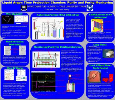
Monitoring Purity by Drifting Electrons
- The wires have a capacitance of 12 pF/m this
capacitance affects the signal, so there is a
limit to their length (max. of 600 - 800 pF for
reasonable signal). - The wires structural integrity is stressed
during the process of cooling to the temperature
of LAr
anode grid (V)
cathode grid (0V)
- Electrons are ejected from a photocathode by a Xe
lamp and drifted to the anode - Cathode and anode signals are compared to
determine drift-time (see bottom left)
Qanode/Qcathode e-tdrift/? - O2 concentration 3E-13 / ? (in seconds)
- We have achieved drift lifetimes of 12ms which
meets the specifications for a 3m drift and a 20
loss. - Next we plan on testing the effect of impurities
(other than oxygen and water) with the apparatus
directly below.
- The LArTPC provides very clear tracks by
producing bubble-chamber-like images from
wire-plane readouts and provides for total
absorption calorimetry. - However, larger detectors (and consequently new
technology) are needed
Long wire test set-up
Electron Flow due to E field
(ex-) Village Water Tank Project
How It Works
G. Carugno et. al., NIM A292 (1990)
anode (V)
photocathode (-V)
Air
anode signal
Out of service for decades
Argon gas
photodiode
Carlo Rubia
drifttime
- Ionization electrons from passing charged
particles are drifted over meters to wire chamber
readout planes which detect the electrons in
predictable ways (right). - Each drift region is surrounded by a field cage
to ensure a uniform E field. - Each set of signal wires consists of 3 wire
planes offset at known angles (left).
- Such a large vessel cannot be evacuated, a
considerable challenge when the removal of oxygen
is paramount. - We are exploring using argon gas as piston
(right) to displace the air from a large tank,
requiring fewer volume changes to achieve a low
level of oxygen contamination. - Data from tests on a small tank at PAB show that
our approach has great promise.
Qcathode
cathode signal
M 40.0 µs 12.5 MS/s
tdrift 150 ?s, Qanode/Qcathode 1
Recommended
CrystalGraphics Presentations


