
Coupling impedance study of the SPS cold to warm transitions - PowerPoint PPT Presentation
1 / 1
Title:
Coupling impedance study of the SPS cold to warm transitions
Description:
Coupling impedance study of the SPS cold to warm transitions B. Spataro, D. Alesini, LNF-INFN, Frascati, Italy; M. Migliorati, A. Mostacci, L. Palumbo, University of ... – PowerPoint PPT presentation
Number of Views:57
Avg rating:3.0/5.0
Title: Coupling impedance study of the SPS cold to warm transitions
1
Coupling impedance study of the SPS cold to warm
transitions B. Spataro, D. Alesini, LNF-INFN,
Frascati, Italy M. Migliorati, A. Mostacci, L.
Palumbo, University of Rome "La Sapienza'',
Italy F. Ruggiero, CERN, Switzerland.
In many papers, the interaction between a
relativistic particle beam and a vacuum chamber
with holes is usually described in terms of
coupling impedance and loss factor. The
interference among the holes is the main source
of wake fields and losses. This note focuses on
the impedances evaluation of SPS cold to warm
transitions. A comparison between an analytical
model and the numerical results is presented.
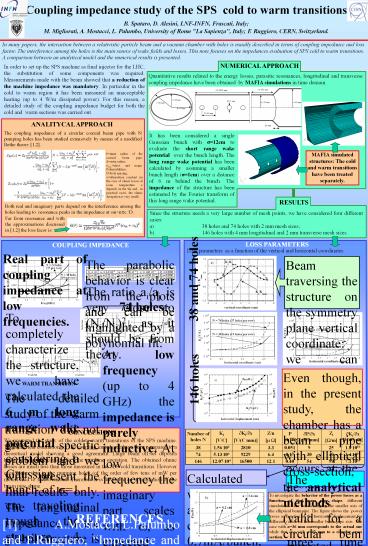
NUMERICAL APPROACH
In order to set up the SPS machine as final
injector for the LHC, the substitution of some
components was required. Measurements made with
the beam showed that a reduction of the machine
impedance was mandatory. In particular in the
cold to warm region it has been measured an
unacceptable heating (up to 4 W/m dissipated
power). For this reason, a detailed study of the
coupling impedance budget for both the cold and
warm sections was carried out.
Quantitative results related to the energy
losses, parasitic resonances, longitudinal and
transverse coupling impedance have been obtained
by MAFIA simulations in time domain.
ANALITYCAL APPROACH
The coupling impedance of a circular coaxial beam
pipe with N pumping holes has been studied
extensively by means of a modified Bethe theory
1,2.
It has been considered a single Gaussian bunch
with s12cm to evaluate the short range wake
potential over the bunch length. The long range
wake potential has been calculated by assuming a
smaller bunch length (s1cm) over a distance of 6
m behind the bunch. The impedance of the
structure has been estimated by the Fourier
transform of this long range wake potential.
MAFIA simulated structures The cold and warm
transitions have been treated separately.
binner radius of the coaxial beam pipe douter
radius ae,m,elect. and magn.
Polarizabilities Dhole spacing aattenuation
constant (in the case of ohmic losses at room
temperature a depends on the ?? and, in
practical cases, the ohmic dissipation is very
small).
RESULTS
Both real and imaginary parts depend on the
interference among the holes leading to
resonance peaks in the impedance at ?nn?c /D.
Since the structure needs a very large number of
mesh points, we have considered four different
cases a) 38 holes and 74 holes with 2 mm mesh
sizes b) 146 holes with 4 mm longitudinal and 2
mm transverse mesh sizes.
Far from resonance and with the approximations
discussed in 1,2 the loss facor is
LOSS PARAMETERS
COUPLING IMPEDANCE
Loss parameters as a function of the vertical
and horizontal coordinates.
Real part of coupling impedance at low
frequencies.
The parabolic behavior is clear from the plots
and can be highlighted by a polynomial fit.
The ratio ai/aj is very close to (Ni/Nj)2 as it
should be from theory.
74 holes
38 and 74 holes
To completely characterize the structure, we have
calculated the 6 m long range wake potential
considering a Gaussian bunch of s1 cm traveling
trough the structure 4 mm away from the holes.
The Fourier transform of this wake potential
gives the impedance of the structure at that beam
position.
At low frequency (up to 4 GHz) the impedance is
purely inductive. At low frequency the imaginary
part scales with ?, as expected from theory. The
real part is proportional to ?2 and exhibits
resonant peaks. The maximum amplitude of the
resonances depends on the proximity of the beam
to the slotted wall, but they are always present.
In the simulations, their amplitude scales with
N. The parasitic resonances in the 4-12 GHz
frequency range are very far from the bunch
spectrum cut-off. It is worth noticing that the
strongest resonance is peaked at about f9.27
GHz. This frequency corresponds to a wavelength
equal to the holes distance.
Even though, in the present study, the chamber
has a beam pipe with elliptical cross-section,
the analytical methods (valid for a circular bem
pipe) remains extremely useful to check the order
of magnitude of the discussed numerical results.
As a result for the cold transition with a number
of holes N146, by assuming an internal radius
equal to b4.3 cm we obtain Z/n12.3 µO and
P0.55mW. Instead asuuming an equivalent chamber
radius 3 beq3.74 cm, we get Z/n16.5 µO and
P0.43 mW. Both results are in good agreement
with the simulation ones.
WARM TRANSITION
The detailed study of the warm transition did not
give specific problem and we will present the
final results only. The longitudinal impedance of
the global structure is estimated to be Z/n0.31
mO. The vertical transverse impedance is Zty707
O/m while the horizontal one is Ztx382 O/m.
146 holes
CONCLUSIONS
Number of holes N Kl V/C ?Kl/?x V/(C mm) Z/n ? ? P mW ?P/?x ?W/mm Zt ?/m ?Kt/?x V/(C m)
38 1.56.104 2810 3.3 0.051 9 25 1.8.1010
74 5.13.104 9229 6.4 0.17 30 49 3.4.1010
146 12.07.104 16500 12.1 0.40 54 99 7.1.1010
We presented the study of the cold to warm
transitions of the SPS machine. The numerical
estimations of the coupling impedance have been
compared to a theoretical model showing a good
agreement. Large beam off-set deposits higher
power that could affect the machine operation.
The obtained ohmic losses are much less than
those measured in the SPS cold transitions.
However even losses due to the pumping holes (of
the order of few tens of mW per meter) lead to
heat overload. Therefore it is advisable an
optimization of the beam pipe shape.
Calculated with an average current of
0.7mA/bunch, a revolution time of T23 ? s and a
number of bunches Nb288.
The horizontal transverse loss factor is three
time higher than the vertical one. For this
reason we present results related only to the
horizontal case.
To investigate the behavior of the power losses
as a function of the beam pipe shape, different
simulations were done changing the smaller axis
of the elliptical beampipe. The figure shows the
power losses as function of the horizontal
displacement for different values of the smaller
beam pipe axis. The case with a36 mm corresponds
to the actual one while that one with a42 mm to
a circular cross section.
REFERENCES
1 A.Mostacci, L.Palumbo and F.Ruggiero,
Impedance and loss factor of a coaxial liner
with many holes effect of the attenuation'',
Phys.Rev.ST-AB,\bf 2,124401, 1999. 2 A.
Mostacci, Energy lost by a particle beam in a
lossy coaxial liner with many holes, LHC Project
Report 199, February 2002. 3 L. Palumbo, et
al., Coupling Impedance in a Circular Particle
Accelerator, a Particular Case Circular Beam,
Elliptical Chamber, IEEE Trans. on Nuclear
Scienze, Vol. NS-31, n. 4, August 1984.