

Prototype SKA Technologies at Molonglo: PowerPoint PPT Presentation
1 / 1
Title: Prototype SKA Technologies at Molonglo:
1
Prototype SKA Technologies at Molonglo 3.
Beamformer and Correlator J.D.
Bunton Telecommunications and Industrial Physics,
CSIRO. Australia.
Photo D. Bock
Correlator The digital filterbanks use the same
technology as the the ATNF 2 GHz filterbanks. It
is estimated that one XC2V6000 field programmable
gate array (FPGA) is needed per filterbank. See
A 2 GHz Digital Filterbank Correlator (this
meeting) for more details. The correlator
cross-multiply-accumulate units (XMACS) are also
implemented in FPGAs and operate at 125 MHz. At
this speed each FPGA implements 36 XMACS, each
with 1024 complex 36-bit accumulators. Two 125
MHz banks of XMACs are used to process the full
250 MHz bandwidth. About 100 FPGAs are needed to
implement a full correlator for each Stokes
parameter. Spectral line observation will be
implemented using decimation in the filterbank
and FXF techniques. For this system 768-lag XF
correlations can be implemented in each bank of
the XMACs. This allows for a further 500 fold
increase in resolution beyond that provided by
the digital filterbank.
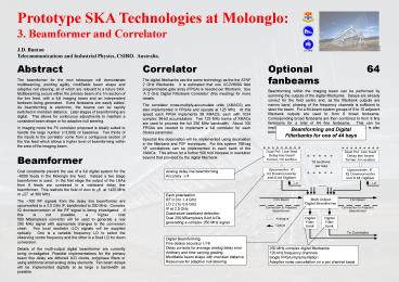
Optional 64 fanbeams Beamforming within the
imaging beam can be performed by summing the
outputs of the digital filterbanks. Delays are
already correct for the field centre and, as the
filterbank outputs are narrow band, phasing of
the frequency channels is sufficient to steer the
beam. For a 64-beam system groups of 8 to 10
adjacent filterbank outputs are used to form 8
broad fanbeams. Corresponding broad fanbeams are
then combined to form 8 fine fanbeams for a total
of 64 fine fanbeams. This can be implemented in
a total of 64 FPGAs. FFT beamforming is also
being investigated.
Abstract The beamformer for the new telescope
will demonstrate multibeaming, pointing agility,
modifiable beam shape and adaptive null steering,
all of which are relevant to a future SKA.
Multibeaming occurs within the primary beam of a
1m section of the line feed, with a full imaging
beam and an independent fanbeam being generated.
Extra fanbeams are easily added. As beamforming
is electronic, the beams can be rapidly switched
in meridian distance. Later stages of
beamforming are digital. This allows for
continuous adjustments to maintain a consistent
beam shape or for adaptive null steering. In
imaging mode the FX correlator proposed is
ideally suited to handle the large number
(gt3,000) of baselines. Two thirds of the inputs
to the correlator come from a contiguous section
of the line feed which allows a higher level of
beamforming within the area of the imaging beam.
Beamformer Cost constraints prevent the use of
a full digital system for the 6000 feeds in the
Molonglo line feed. Instead a two stage
beamformer is used. In the first stage the
output of the LNAs from 9 feeds are combined in a
wideband delay line beamformer. This restricts
the field of view to ?6 at 1420 MHz or ?27 at
300 MHz. The 700 RF signals from the delay line
beamformer are upconverted to a 2.5 GHz IF,
bandlimited to 250 MHz. Complex IQ
downconversion of the RF signal is being
investigated. If this is not possible, a higher
cost 500 MSamples/s converter will be used to
generate a real 250 MHz signal with appropriate
changes to the conversion chain. Two local
oscillator (LO) signals will be supplied
optically. One is a variable frequency LO to
select the observing centre frequency and the
other is a fixed LO for down conversion. Details
of the multi-output digital beamformer are
currently being investigated. Possible
implementations for the primary beam fine delay
are dithered A/D clocks, polyphase filters or
using additional small analog delay elements.
Fan beam delays will be implemented digitally at
as large a bandwidth as possible.
Beamforming and Digital Filterbanks for one of 44
bays
Analog delay line beamforming Accuracy ?/4
Each polarisation RF 0.3 to 1.4 GHz LO 2.2 to 0.9
GHz IF at 2.5 GHz Quadrature baseband
detection Dual 250 MSamples/s 8-bit A/Ds
generating a complex 250 MHz signal
Digital Beamforming Fine delays accuracy
?/16 Delay corrects for average analog delay
error Arbitrary and time varying
grading Modifiable beam shape with meridian
distance Resources for adaptive null steering
250 MHz complex digital filterbanks 120 kHz
frequency channels Single FPGA implementation
Adaptive noise cancellation on a per channel
basis
Recommended

