
Aim:- PowerPoint PPT Presentation
1 / 9
Title: Aim:-
1
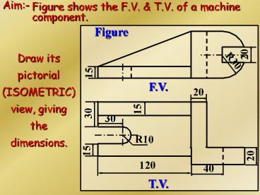
Aim-
Figure shows the F.V. T.V. of a machine
component.
Figure
20
Draw its pictorial (ISOMETRIC)view, giving the
dimensions.
R30
15
F.V.
20
15
30
30
R10
15
20
120
40
T.V.
2
Note 1- The machine component is splitted into
four different parts, for its iso. sketching,
with bottom base part as first drawn.
Note 2-The circularity or part of that of
Ortho.View, is to be drawn in Iso view as an
ellipse or part of that using four center
method,as explained earlier.
Note 3- Such components may be drawn in iso., by
area (plane)wise w.r.t F.V, T.V S.V
directions. Never prefer box method for such
components.
3
20
Solution
Split-II
60
See, Note 2
20
20
Split-III
15
R30
20
Split-IV
65
15
ISOMETRIC VIEW
R10
30
Split-I
120
30
See, Note 2
15
4
Aim- Sketch shows the Orthographic views of a
machine component. Draw its appropriate Isometric
view, using splitting the object into pieces
techniques. Give the dimensions on the ISOMETRIC
VIEW drawn.
5
T.V.
F.V.
6
Dimensions must be given on the Isometric view,
which are not shown here.
C
B
R15
D
A
7
Exercise
Figure shows the Orthographic views of a machine
component. Draw its Isometric view. Give the
dimensions as per aligned system.
8
c
b
a
FRONT VIEW
L.H.S.V.
FIGURE
NOTE- The front view areas are A B,
while the side view areas are a, b c.
9
Solution
B
c
b
a
A
ISOMETRIC VIEW
Recommended
