
Designing a 90% efficiency 150W power supply with PFC in hours PowerPoint PPT Presentation
Title: Designing a 90% efficiency 150W power supply with PFC in hours
1
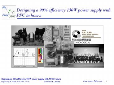
Designing a 90 efficiency 150W power supply with
PFC in hours
2
Next 2.5 hours
- 230 245 Old vs New
- 245 315 Active Diode IC
- 300 315 EMI Cancellation IC
- 315 345 Design Methodology How we trained?
- 345 400 Tea Break
- 400 445 Designed by PowerEsim New design
procedure - 445 500 QA
3
Old
VS
New
4
Old engineer vs Young engineer
20 years ago . . . . For a MOSFET Conduction
loss 1/3 Switching loss 2/3
20 years old . . . . For a MOSFET Conduction
loss 2/3 Switching loss 1/3
5
Old MOSFET VS Young MOSFET
47 ns vs 5 ns, 10 times different
6
Where is the ZVS ?
Adaptor A efficiency demanding product. How
many of them are using ZVS circuit?
7
Where is the ZVS ?
Active Clamp ? 2 Switch Forward
Full Bridge ? Phase Shift Bridge
Asym. Half-Bridge ? Half-Bridge
8
Where is the losses?
Example 12V_at_4A 82 10W loss
15
25
30
10
9
Where money can buy
- Pay for ZVS
- Pay for lower Rds
- Pay for lower tr, tf . .
10
- After all, it is only 10
10
Where money cant buy
Copper Ferrite
Band Gap Loss
Copper Loss
11
Why not use less copper?
- Active EMI Filter
- WT6001 Y-Cap Booster
- Next section
Old
New
12
Why not of not using diode?
Old
New
- STPS20H100
- 0.6V _at_ 27A 100 deg
- TO200 package
- USD ?? / pcs
- IRF540Z 22m Ohm
- 0.54V _at_ 14A 100 deg
- TO200 package
- USD ?? / pcs
13
If TO220 has the same price . . .
- Active Diode
- WT6002 active diode IC
- Next section
- STPS20H100
- 0.6V _at_ 27A 100 deg
- TO200 package
- USD ?? / pcs
- IPP05CN10 5m Ohm
- 0.08V _at_ 14A 100 deg
- TO200 package
- USD ?? / pcs
14
Transformer design calculation
- After all those mathematics, how will it perform ?
15
Mathematics for the loss
- Do you calculate it every time on your design
stage?
16
What exactly you are doing?
Do?
Np ?
Co?
Wire ?
Ns ?
Wire?
M1?
- Just simple fill in the blank
17
Transformer core and wire only
- PowerEsim It is not giving parameters for play
with design, It is a tool to build the design.
18
98 VS 99 - not 1 different
- 98 efficiency
- 2 loss
- 30W loss
- 99 efficiency
- 1 loss
- 15W loss
- Efficiency is not just a figure, it does matter.
19
98 VS 99 - 200 different
- 98 efficiency
- 2 loss
- 150W converter
- 99 efficiency
- 1 loss
- 300W converter
- Selling price double by 1 losses cut
20
What is all about
- Active Diode vs Diode almost same cost.
- EMI IC vs filter greatly improve efficiency.
- PowerEsim vs Paper design no cost.
21
Active Diode EMI IC
22
EMI solutions Passive filter
- Conventional EMI solutions depend on passive
filter using inductors and capacitors - Inductors CMC, DMC
- Capacitors X-cap, Y-cap
- There are limitations when using passive filters
- Inductors Large size and high conduction loss
- Capacitors leakage current specifications
23
Active EMI cancellation IC WT6001An effective
EMI solution Y-cap booster
WT6001
- A patented technology developed in PowerELab.
- An SO-8 IC WT6001 developed with W2.
- Equivalent to a Y-cap with very large value
within the EMI concerned frequency range only. - No boosting effect in the leakage current test
concerned frequency range (50 800Hz). - Greatly reduce the common mode inductor size and
requirements. - Reduce converter size and improve conversion
efficiency. - Provide effective and efficient EMI solution.
- Built-in electrical surge protection which can
easily pass the EN61000-4-4 and EN61000-4-5
immunity standard.
24
Applications Replace passive Y-cap
Replaced by Y-cap booster
LISN
25
Effect measurable by oscilloscope when using
Y-cap booster
Noise voltage across Y-cap in switching converter
Noise voltage across Y-cap booster in switching
converter
More application examples can be found in the
datasheet of WT6001
26
Practical application examples
- The original EMI filter design cannot pass the
EN55022 class B limit. - Filter component
- 2 x 20mm high mu toroid for common mode filters
- 2 x 0.15uF X cap
- 1 x 1n Y1-cap connected between primary and
secondary
27
Practical application examples Original filter
schematic
- It is a commonly used filter configuration
- L2B is wound with many turns which intends to
suppress the low to mid-frequency common mode
noise. Its leakage inductance together with C1
also provides differential mode noise filtering - L1B is a single layer, bi-filer wound common mode
choke for high frequency common mode noise
filtering
28
Practical application examples EMI measurement
Y-cap From 1n to 3n3
DM noise
Improved but not enough
CM noise
- Failure was identified to be caused by
- Insufficient leakage inductance of the common
mode choke for DM noise attenuation. - The two common mode choke cannot effectively
block out the common mode current. - Further increase of Y-cap can reduce CM noise but
fail to meet leakage current specifications.
29
Practical application examples Solution using
Y-cap booster
- Y-cap booster is used to replace the primary to
secondary Y-cap - After using the Y-cap booster, L2B is replaced by
a small differential mode filter and L1B is
reduced to a 9mm toroid with only a few turns to
tackle the high frequency common node noise. The
test results pass the required limit lines
30
Practical application examples Filter
comparison Before and After...
Passed design using Y-cap booster with much
smaller filter size that saves cost, power and
space
Failed design even with more cost, loss and
bigger size for the filter
31
Another practical application examples Filter
comparison Before and After...
Original EMI solution using passive filter in ATX
converter
New EMI solution using Y-cap booster in ATX
converter
32
Conclusion
- Y-cap booster breaks the relationship between the
Y-cap values and leakage current requirement. - Greatly reduce product design period and
resources. - It can be applied to any position with
conventional Y-cap. - Significantly reduce the size and loss of common
mode choke implies higher power density and
efficiency. - EMI less sensitive to transformer winding
capacitance implies more rooms for improving
transformer coupling. - Very suitable for equipment required low leakage
current like medical equipment.
33
Active Diode An easy to use and high efficiency
rectifier suitable for all converters
- Stringent requirements of nowadays converters
- Compact size
- Low heat generation and high conversion
efficiency - High output power and output current
- Low cost
- !!!
- Conventional technologies cannot meet the
requirements!!
34
Synchronous rectifier
- Use MOSFETs to replace diode rectifiers.
State of the Art 30V SCK
Average 30V SO8 MOSFET
35
Synchronous rectifier
- Provides low conduction loss.
- Can operate at higher high current without
heatsink.
MOSFET 0.7W losses _at_ 10A
36
Synchronous rectifier
- Usage not limited to converters with high profit
margin. - Price of nowadays low RDSon MOSFETs comparable to
schottky diodes using the state of the art
technology. - Provide even lower converter cost because of
reduced heatsink, more output power, higher
conversion efficiency.. - Emerge in low cost converter like adaptors,
standard open frame converters, ATX .
37
Synchronous rectifier
AD
AD
- Problematic for some conventional topologies
- Special and sometimes complicated driving
circuits SR - are needed for different topologies
- Performance sensitive to transformer leakage
- inductance and operating conditions
- Converter cannot be paralleled Reverse current
- Poor efficiency at low load
- Limited input voltage range
- Simple circuit
- Discontinuous mode is allowed
- Good low load efficiency
- Converter can be paralleled
- High conversion efficiency
- Works just like a diode
38
Active diode Operating principle
A
K
A1
N1
N2
N3
N4
- N1 is the current sense winding
- N2 provides MOSFET driving signals
- A1 driver circuit (IC WT6002)
- N1 N3 D1 form energy recovery circuit
- N4 D2 form reset circuit
D2
D1
39
Active diode Operating principle
Voltage across winding N2 or gate drive voltage
Von of SR depends on ratio of N2 to N3 and
voltage Vo
Toff
Ii
Von
VN2
Voltage source Vo can be any voltage source in
a converter, e.g. output voltage
Vo
VN3
Vo
VN4
40
Application of Active Diode in different
topologies
L
f
C
V
Freewheel
Magnetic
o
o
C
V
Vin
Reset
SR
o
o
-
-
Vin
S
Flyback SR
-
S
Forward SR
-
Flyback
Forward
41
Application of Active Diode in different
topologies
L
L
f1
f
S
S
SR1
C
C
1
1
1
1
C
SR1
C
V
o
o
o
-
Vin
Vin
SR
2
S
S
C
-
C
V
2
SR
2
2
L
-
2
2
o
f2
-
Half Bridge centre tap
Current Doubler
42
Application of Active Diode in different
topologies
SR1
C
V
o
o
-
I
and many others.
SIN
SR
2
Resonant converter
43
Successful application of Active Diode in
converter products
AD on 120W ACDC
AD on 1.5 V 200 A ACDC
44
Conclusion
- A new Active Diode technology is presented.
- A kind of current driven synchronous rectifier
technology that provides high conversion
efficiency and eliminates many conventional
synchronous rectifier application problems. - Patented technologies.
- An Active Diode driver IC WT6002 for easy
implementation of the technology. - Well proven by many converter product design.
45
References
- Liu, J.C.P. Poon, F.N.K. Xuefei Xie Pong,
M.H. current driven synchronous rectifier with
energy recovery sensor Power Electronics and
Motion Control Conference, 2000. Proceedings.
PIEMC 2000. The Third International , Volume 1 ,
2000, page(s) 375 -380 vol.1 - Xuefei Xie Liu, J.C.P.L. Poon, F.N.K. Man Hay
Pong Current-driven synchronous rectification
technique for flyback topology, Power Electronics
Specialists Conference, 2001. PESC. 2001 IEEE
32nd Annual , Volume 1 , 2001, Page(s) 345 -350
vol. 1 - Xuefei Xie Liu, J.C.P. Poon, F.N.K. Man Hay
Pong A novel high frequency current-driven
synchronous rectifier for low voltage high
current applications, Applied Power Electronics
Conference and Exposition, 2001. APEC 2001.
Sixteenth Annual IEEE , Volume 1 , 2001,
Page(s) 469 -475 vol.1 - Liu, J.C.P. Xuefei Xie Poon, F.N.K. Pong,
B.M.H. Practical solutions to the design of
current-driven synchronous rectifier with energy
recovery from current sensing, Applied Power
Electronics Conference and Exposition, 2002. APEC
2002. Seventeenth Annual IEEE , Volume 2 , 2002,
Page(s) 878 -884 vol.2 - Xuefei Xie Joe Chui Pong Liu Poon, F.N.K. Man
Hay Pong A novel high frequency current-driven
synchronous rectifier applicable to most
switching topologies, Power Electronics, IEEE
Transactions on , Volume 16 Issue 5 , Sep 2001,
Page(s) 635 -648 - Xie Xuefei Liu, J.C.P. Poon, F.N.K. Pong,
B.M.H. Two methods to drive synchronous
rectifiers during dead time in forward
topologies, Applied Power Electronics Conference
and Exposition, 2000. APEC 2000. Fifteenth Annual
IEEE , Volume 2 , 2000, Page(s) 993 -999 vol.2 - US patent "Current driven synchronous rectifier
with energy recovery" patent number 6,134,131 - US patent Self-driven synchronous rectifier by
retention of gate charge patent number 6,377,477
- US patent Current driven synchronous rectifier
with energy recovery using hysterisis driver,
patent number 6,597,587
46
We are trained to
fill in a value
NOT
design a circuit
47
Fill in values by experience . . .
Vi100 Vo12 VoViDNs /
(1-D)Np ViVoNp/Ns0.8Vds_max VoNs0.3fs/(
1-D) 0.5Vo_rippleQ/Co Vds_max_M1lowerest
cost in stock Ids_max_M1lowerest cost in
stock IF_max_Do2Io VR_max_Do1.2(ViNs/NpVo)
Core_T1recommended table from ferrite
manufacturer Wire_Npfully filled Wire_Nsfully
filled
48
Then again . . .
- Replace 100pcs of components at bench
49
Fine, but no need to replace at the bench . . .
- Why not replace 100pcs of components at PowerEsim
50
www.powerEsim.com
- Its on-line
- Its for everyone
- Worldwide access
- 100 server side simulation
- Its free
51
Build virtual and real converter
PFC Developed under Infineon TDA4863 Evaluation
Design
DC-DC Developed under Infineon ICE3DS01
Evaluation Design
150W 90 LCD Converter
52
160 W PFC simulation vs measurement
Measured
PowerEsim
53
150 W Flyback simulated vs measured
Measured
PowerEsim
54
Loss and Temp.
55
Component Based Approach
Real components
Abstract Concept
- RdsCrss
- Vftrrm
- CV
- k1, k2, k3
- Current density
- Find MOSFET
- Find Diode
- Find Capacitor
- Find Core
- Find Wire
56
PowerEsim vs Traditional Design
PowerEsim turn design into
result oriented adaptive iteration
instead of
skill of knowledge application
57
But first . . .
- Find a circuit that has closest specification to
your need, e.g. 160W TDA4863 for PFC front end.
58
Ask our expert
- Enter the input output specification
- Chose an application
- Click Recommend Design
59
How our expert system work.
60
If you like more freedom
- Click Topologies
- Chose the topology you like
- Enter the input output specification
61
Re-define specification
- Click Detail Spec.
- Change specification as you like
62
Click the main MOSFET
63
How we model component?
64
Click, click, click and select
- A particular one total individual loss
- Highlighted one total, individual loss and
stress - Selected one total individual loss and stress
65
Other than loss, Stress is important
66
More clever method Smart Optimizer
Click Select All
All MOSFET will dump into a optimizer pool
67
Smart Optimizer just a click
- Enter maximum iterations
- Wait a few seconds
- Click Smart Optimizer
68
Multi dimensional optimization
10 resistor
1
x
10 MOSFET
2
x
x
10
10 diode
1010 combination
31 years simulation
69
Smart Optimizer how it work
Data set
Smart Scan Search for good component
Genetic Algorithm
BU60
BU60
SPD07N60C3
SPD07N60C3
SPN04N60C2
SPN04N60C2
SPB07N60S5
SPB07N60S5
IPP50R520CP
IPP50R520CP
70
Sorted one by one
- Result will be ranked
- Click to view each result
- Optimized Component will be shown
71
Now Active Diode
- Click the diode you like to replace by Active
Diode or Sync Rect.
- In the Component Finder, change its Rectifier
Type to Active Diode
72
Search more MOSFET
- Extend to higher current range is usually needed
- Extend the body diodes trrm can find more MOSFET
73
Select a better Sync Rect.
- 0.5W Active Diode loss
- 2.54W SCK loss
74
Which component is more critical?
- Why M1, D3 T1
- Loss Analysis the most useful page
- It rank the loss and its details
75
Follow the step
- Follow the tips from the header is a good
practice. - Just click the box, it will redirect you to other
tools - Go through each box step by step
76
Click T1 and go to Magnetic Builder
77
Step 1 select the core you like
- Chose the range of Ae
- Select Core shape
- Select Manufacturer
78
Instant preview winding when thing change
- Click the preview winding
- Corresponding winding cross section will be shown
- Supported on Core, N and Wire.
79
Step 2 find the best Lm
- Click the Inductance button
- Enter the range of inductance
- Highlight each in the list, select according to
total loss and stress. - Double check OCP is not be triggered.
80
Step 3 find the best N0
- Click the Number of turn button
- Enter the range of turn
- Highlight each in the list, select according to
total loss and stress. - Double check OCP is not be triggered.
81
Dont forget preview winding
- Click the Preview Winding button
- Observe how winding structure change with number
of turn.
82
Step 4 need more copper?
- Click the Change Wire button
- Click the No. of Parallel Wire
- Add more parallel wire as you like.
83
160 W PFC simulation vs measurement
Measured
PowerEsim
84
150 W Flyback simulated vs measured
Measured
PowerEsim
85
DVT check the stresses
- DVT Report check every components stress and also
circuit design constraint.
86
Thermal knowing Temp. at day 1
87
MTBF how long it last
88
Designing a 90 efficiency 150W power supply with
PFC in minutes
- Live Demonstration
Recommended
