
Liquid-Liquid Extraction PowerPoint PPT Presentation
1 / 76
Title: Liquid-Liquid Extraction
1
Liquid-Liquid Extraction
2
Hierarchy of Separation Technologies
3
Typical Applications
- Remove products and pollutants from dilute
aqueous streams - Wash polar compounds or acids/bases from organic
streams - Heat sensitive products
- Non-volatile materials
- Azeotropic and close boiling mixtures
- Alternative to high cost distillations
4
Extraction is Used in a Wide Variety of Industries
Chemical Washing of acids/bases, polar compounds from organics
Pharmaceuticals Recovery of active materials from fermentation broths Purification of vitamin products
Effluent Treatment Recovery of phenol, DMF, DMAC Recovery of acetic acid from dilute solutions
Polymer Processing Recovery of caprolactam for nylon manufacture Separation of catalyst from reaction products
Petroleum Lube oil quality improvement Separation of aromatics/aliphatics (BTX)
Petrochemicals Separation of olefins/parafins Separation of structural isomers
Food Industry Decaffeination of coffee and tea Separation of essential oils (flavors and fragrances)
Metals Industry Copper production Recovery of rare earth elements
Inorganic Chemicals Purification of phosphoric acid
Nuclear Industry Purification of uranium
5
Removal of Organics From WaterDistillation vs.
Extraction
Organic Compound BP C Water Solu. Azeotrope B.P. C Azeotrope B.P. C Azeotrope Water Typical Reduction Level
Methylene Chloride 40 2.0 38.1 38.1 1.5 lt 50 ppb
Acetone 56.2 Infinite Non Azeotropic Non Azeotropic Non Azeotropic lt 50 ppb
Methanol 64.5 Infinite Non Azeotropic Non Azeotropic Non Azeotropic lt 50 ppb
Benzene 80.1 0.18 69.4 8.9 8.9 lt 50 ppb
Toluene 110.8 0.05 85.0 20.2 20.2 lt 50 ppb
Formaldehyde -21 Infinite Non Azeotropic Non Azeotropic Non Azeotropic lt 1,000 ppm
Formic Acid 100.8 Infinite 107.1 22.5 22.5 lt 500 ppm
Acetic Acid 118.0 Infinite Non Azeotropic Non Azeotropic Non Azeotropic lt 500 ppm
Pyridine 115.5 57 92.6 43 43 lt 10 ppm
Aniline 181.4 3.60 99.0 80.8 80.8 lt 10 ppm
Phenol 181.4 8.20 99.5 90.8 90.8 lt 10 ppm
Nitrobenzene 210.9 0.04 98.6 88.0 88.0 lt 10 ppm
Dinitrotoluene (2,4) 300.0 0.03 99 100 gt 90 gt 90 lt 10 ppm
Dimethyl Formamide 153.0 Infinite Non Azeotropic Non Azeotropic Non Azeotropic lt 10 ppm
Dimethyl Acetamide 166.1 Infinite Non Azeotropic Non Azeotropic Non Azeotropic lt 10 ppm
n-Methylpyrrolidone 202.0 Infinite Non Azeotropic Non Azeotropic Non Azeotropic lt 10 ppm
Distillation
Extraction
6
Simple Extraction Single Stage
7
Cross Flow Extraction
8
Countercurrent Flow Extraction
9
Countercurrent Extraction
B C
Extract (E) Solute Rich Stream
A B
Primary Interface
Feed (F)
Continuous Phase
Dispersed Phase
C
Solvent (S)
Raffinate (R) Solute Lean Stream
A
10
Bench Scale Test Apparatus
11
Simple Extraction
12
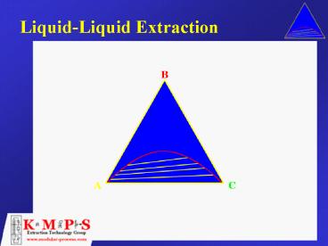
Typical LLE Equilibrium Curve
Extract Composition (Wt Fract., Solute Free)
Raffinate Composition (Wt Fract., Solute Free)
13
Graphical Determination of Theoretical Stages95
Solute Extraction, S/F 1.0 mass basis
(0.136, 0.114)
Extract Composition (Wt Fract., Solute Free)
Raffinate Composition (Wt Fract., Solute Free)
14
Graphical Determination of Theoretical Stages98
Solute Extraction, S/F 1.0 mass basis
(0.136, 0.118)
Extract Composition (Wt Fract., Solute Free)
Raffinate Composition (Wt Fract., Solute Free)
15
Kremser Equation
Where n Number of theoretical stages
required xf Conc. of solute in feed on
solute free basis xn Conc. of solute in
raffinate on solute free basis ys Conc. of
solute in solvent on solute free
basis m Distribution coefficient E Extractio
n factor (m)(S/F)
16
Engineering CalculationsKremser Type Plot
17
Typical Extraction System
BC(A)
Feed
AB
Raffinate Stripping
Solvent Recovery
Extraction
C (A)
C (AB)
Solvent
C
(AB)
A(BC)
A (BC)
B (C)
18
Removal of Phenol from Wastewater
19
Recovery of Acetic Acid from WaterUsing a Low
Boiling Solvent
20
Recovery of Carboxylic Acids from
WastewaterUsing a High Boiling Point Solvent
21
Neutralization/Washing of Acid or Baseor Polar
Compounds from Organic Stream
Organic
Water
Organic Feed could contain caustic.
Mid- Feed would be mild acid.
Extraction
Caustic (Mild)
Feed (Organic Acid)
Water Salts
22
Series Extraction
23
Recovery of Caprolactam
24
Phosphoric Acid Purification via Extraction
25
Organo-Metallic Catalyst Recovery
26
Fractional ExtractionProcess Scheme
(A-Rich)
YAE,YBE
XAS2,XBS2
NR
XAF,XBF
NS
XAS1,XBS1
(B-Rich)
XAR,XBR
27
Extraction of Flavors andAromas
Typical Products Orange Oil Lemon Oil
Peppermint Oil Cinnamon Oil
28
Separation of StructuralIsomers
Typical Applications m. p. - Cresol
Xylenols 2 , 6 - Lutidine 3 , 4 -
Picoline
29
Major Types of Extraction Equipment
Column Contactors
Mixer Settlers
Centrifugal
Used primarily in the metals industry due to
- Large flows - Intense mixing - Long
Residence time - Corrosive fluids -
History
Used primarily in the pharmaceutical industry due
to - Large flows - Intense mixing
- Long Residence time - Corrosive fluids
- History
Static
Agitated
Spray
Packed
Tray
Pulsed
Rotary
Reciprocating
Rarely used
Used in - Refining -
Petrochemicals Example - Random -
Structured - SMVPTM
Used in - Refining -
Petrochemicals Example - Sieve
Used in - Nuclear - Inorganics -
Chemicals Example - Packed - Tray
- Disc Donut
Example - RDC - Scheibel
Example - Karr
Used in - Chemicals - Petrochemicals
- Refining - Pharmaceutical
30
Mix / Decant Tank
- Characteristics
- Mix Settle Phase separate in a single tank
- Batch Processing only
- Requires multiple solvent additions for more than
one stage (crossflow operation) - Typically used for small capacity operations or
intermittent processing
31
Mixer / Settlers
- Characteristics
- Handle very high flowrates
- Good for processes with relatively slow reactions
(residence time required) - Provide intense mixing to promote mass transfer
- Require large amount of floor space
- Suitable when few theoretical stages required
- Large solvent inventory (and losses)
Light Phase In
Heavy Phase Out
32
Centrifugal Extractor
- Characteristics
- Countercurrent flow via centrifugal force
- Low residence time ideally suited for some
pharmaceutical applications - Handles low density difference between phases
- Provide up to several theoretical stages per unit
- High speed device requires maintenance
- Susceptible to fouling and plugging due to small
clearances
33
Packed Column
- Characteristics
- High capacity 20-30 M3/M2-hr (Random)
500-750 gal/ft2-hr (Random) 40-80
M3/M2-hr (Structured) 1,000-2,000 gal/ft2-hr
(Structured) - Poor efficiency due to backmixing and wetting
- Limited turndown flexibility
- Affected by changes in wetting characteristics
- Limited as to which phase can be dispersed
- Requires low interfacial tension for economic
usefulness - Not good for fouling service
34
Sieve Tray Column
- Characteristics
- High capacity 30-50 M3/M2-hr
750-1,250 gal/ft2-hr - Good efficiency due to minimum backmixing
- Multiple interfaces can be a problem
- Limited turndown flexibility
- Affected by changes in wetting characteristics
- Limited as to which phase can be dispersed
35
RDC Extractor
- Characteristics
- Reasonable capacity 20-30 M3/M2-hr
- Limited efficiency due to axial backmixing
- Suitable for viscous materials
- Suitable for fouling materials
- Sensitive to emulsions due to high shear mixing
- Reasonable turndown (40)
36
Scheibel Column
- Characteristics
- Reasonable capacity 15-25 M3/M2-hr
350-600 gal/ft2-hr - High efficiency due to internal baffling
- Good turndown capability (41) and high
flexibility - Best suited when many stages are required
- Not recommended for highly fouling systems or
systems that tend to emulsify
37
Scheibel Column Internal Assembly
38
Karr Reciprocating Column
- Characteristics
- Highest capacity 30-60 M3/M2-hr
750-1,500 gal/ft2-hr - Good efficiency
- Good turndown capability (41)
- Uniform shear mixing
- Best suited for systems that emulsify
39
Karr Column Plate Stack Assembly
40
Pulsed Extractor
- Characteristics
- Reasonable capacity 20-30 M3/M2-hr
- Best suited for nuclear applications due to lack
of seal - Also suited for corrosive applications since can
be constructed out or non-metals - Limited stages due to backmixing
- Limited diameter/height dueto pulse energy
required
41
Comparison Plot of VariousCommercial Extractors
42
Column Selection CriteriaStatic Column
A static column design may be appropriate when
- Interfacial tension is low to medium up to 10-15
dynes/cm - Only a few theoretical stages are required, and
reduction in S/F is not an economic benefit - No operational flexibility required
- There is a large difference in solvent to feed
rates
43
Column Selection CriteriaAgitated Column
Agitated columns are generally more economical
when
- More than 2-3 theoretical stages are required
- Interfacial tension is moderate to high, although
low interfacial tensions may also be economical - A reduction in solvent usage is beneficial to the
process economics - The process requires a wide turndown as well as
the ability to handle a range of S/F ratios
44
Column Selection CriteriaRotating Disc Contactor
(RDC)
- Systems with moderate to high viscosity, i.e. gt
100 cps - Systems that are residence time controlled, for
example, slow mass transfer rate with few
theoretical stages required - Systems with a high tendency towards fouling
45
Column Selection CriteriaScheibel Column
- Systems that require a large number of stages due
to either theoretical stage requirements or low
mass transfer rates - Low volume applications in which a relatively
small column is required - Systems that process relatively easily, without a
tendency to emulsify and/or flood
46
Column Selection CriteriaKarr Reciprocation
Plate Column
- Difficult systems that tend to emulsify and/or
flood easily - Systems in which the hydraulic behavior varies
significantly through length of the column - Sometimes requiring non-metallic internals, such
as Teflon due to wetting characteristics or
corrosive materials - Fouling applications that may have tars
formations and/or solids precipitation
47
The Three Cornerstones of Successful Extraction
Applications
48
Organic Group Interactions
Solvent Class Solvent Class Solvent Class Solvent Class Solvent Class Solvent Class Solvent Class Solvent Class Solvent Class Solvent Class Solvent Class Solvent Class
Solute Class Solute Class 1 2 3 4 5 6 7 8 9 10 11 12
1 Phenol 0 0 - 0 - - - - - -
2 Acid, thiol 0 0 - 0 - - 0 0 0 0
3 Alcohol, water - - 0 0 - -
4 Active H on multihalogen 0 0 0 - - - - - - 0
5 Ketone, amide with no H on N, sulfone, phosphine oxide - - - 0
6 Tertiary amine - - 0 - 0 0 0 0
7 Secondary amine - 0 - - - 0 0 0 0
8 Primary amine, ammonia, amide, with 2H on N - 0 - - 0 0
9 Ether, oxide, sulfoxide - 0 - 0 0 0 0
10 Ester, aldehyde, carbonate, phosphate, nitrate, nitrite, nitrile - 0 - 0 0
11 Aromatic, olefin, halogen, aromatic multihalogen, paraffin without active H, manahalogen paraffin 0 0 0 0 0 0
12 Paraffin, carbon disulfide 0 0 0
1 - 4 H donor groups 5 12 H acceptor
groups 12 Non-H bonding groups
49
Liquid-Liquid Extraction Scale-Up
- Theoretical scale-up is difficult
- Complexity of processes taking place within an
extractor - Droplet Breakup
- Coalescence
- Mass Transfer
- Axial and radial mixing
- Effects of impurities
- Best method of design Pilot testing followed
by empirical scale-up
50
Pilot Plant Configuration
- Determine type of column to be used based on
process considerations - Use the same kind of equipment for the production
unit - Determine diameter and height of pilot column
based on experience
Type of Column Diameter Height
Packed 3 to 4 3 to 6 per Theoretical Stage (TS)
Tray 4 to 6 4 to 5 Trays per TS
Karr 1 1 to 3 per TS
Scheibel 3 3 to 6 Actual Stages per TS (Approx. 3 to 6)
51
Continuous Extraction Pilot Plant Arrangement
52
KMPS Pilot Plant Services Group
KMPS maintains a pilot plant dedicated to
extraction R D and applications testing
53
Possible Extraction Column Configurations
Solvent is Light Phase
E
E
B C
B C
F
F
A B
Primary Interface
A B
Solvent Dispersed
Solvent Continuous
Primary Interface
S
S
C
C
R
R
A
A
Solvent is Heavy Phase
A
A
R
R
Primary Interface
Solvent Dispersed
Solvent Continuous
Primary Interface
E
E
B C
B C
54
Factors Effecting which Phase is Dispersed
- Flow Rate
- For Sieve Tray and Packed Columns disperse the
higher flowing phase - For all other columns disperse lower flowing
phase - Viscosity
- For efficiency disperse less viscous phase
- For capacity disperse more viscous phase
55
Factors Effecting which Phase is Dispersed
- Surface Wetting
- Want the continuous phase to preferentially set
the internals this minimizes coalescence and
therefore maximizes interfacial area. - Importance of maintaining droplets Assume 30
holdup of dispersed phase in 1 M3 of solution
Droplet Diameter m Droplet Volume M3 Number Droplets Droplet SA M2 Interfacial Area M2/M3
100 0.3 7.16x10¹⁰ 1.26x10⁻⁷ 9022
300 0.3 2.65x10⁹ 1.13x10⁻⁶ 2995
500 0.3 5.73x10⁸ 3.14x10⁻⁶ 1796
56
Factors Effecting which Phase is Dispersed
57
Interface Behavior
Actions to control unstable interface As
extraction proceeds, interface normally grows in
thickness and forms a rag layer that stabilizes
at some thickness If rag layer continues to grow,
some action must be taken
- Rag DrawContinuously withdraw a portion of the
interface and pass through a filter to remove
interfacial contamination - Reverse PhasesOften a stable interface can be
controlled by reversing which phase is dispersed
58
Entrainment
59
Flooding
60
Flooding
61
Pilot Tests
62
Extractor Flow Patterns
63
Generalized Scale-up Procedure
Pilot Scale
Commercial Scale
f2
f1
Q1
Q2
Feed Rate
Feed Rate
H1
H2
D1
Basic Scale-up Relationships D2/D1 K1(Q2/Q1
)M1 H2/H1 K2(D2/D1 )M2 f2/f1 K3(D2/D1)M3
D2
Where K1, M1 Capacity Scale-up Factors
K2, M2 Efficiency Scale-up Factors K3,
M3 Power Scale-up Factors
64
Application Scheibel Column
- Extraction of nitrated organics from spent acid
stream using an organic solvent - Reduce nitrated organic compounds from 3.9 to
less than 50 ppm - S/F ratio fixed by process at 3.9
- Equilibrium data indicated that 4.5 theoretical
stages required - Commercial design 3,900 lb/hr (270 GPH) spent
acid feed
65
Scheibel Column Pilot Plant SetupNitrated
Organics Extraction
66
Scheibel Column Pilot Plant Test ResultsNitrated
Organics Extraction
67
Scheibel Column Scale-up ProcedureNitrated
Organics Extraction
14 Dia. 430 GPH/FT2
600
530
Rate in Commercial Column For Dia. 18
Column Capacity For Dia. lt 18
300
GPH/FT2
GPH/FT2
100
157
5
10
15
20
GPH/FT2
IN
Rate in 3 Dia. Pilot Scheibel Column
Scheibel Column Diameter
68
Scheibel Column Pilot Plant Scale-upNitrated
Organics Extraction
- Diameter 14 (D1)
- Expanded Head Diameter 20 (D2)
- Bed Height 9-6 (A)
- Overall Height 16-4 (B)
69
Application Karr Column Alcohol Extraction
from Acrylates
- Extraction of methanol from an acrylate stream
using water as the solvent - Reduce methanol from 2.5 to less than 0.1
- S/F ratio specified by client as 0.32 wt. basis
- Equilibrium data distribution coefficient
generated by KMPS, with average value of 5.3 - Commercial design 36,900 lb/hr (4,660 GPH)
acrylate feed
70
Karr Column Pilot Plant SetupAlcohol Extraction
from Acrylates
Variable Speed Drive
Karr Column 1 Dia. x 8 Plate StackPlate
Spacing from Top 6 of 2 1 of 4
1 of 6316SS Shaft, Plates Spacers
Hot Oil
Raffinate(Acrylate Phase)
Extract(H2O Alcohol)
Water Feed
Acrylate Feed (methyl or ethyl)
Interface
71
Karr Column Pilot Plant Test ResultsMethanol
Extraction from Acrylate
Run Plate Stack Feed Rate cc/min Water Feed Rate cc/min Agitator Speed SPM Interface Raffinate Conc. Alcohol Raffinate Conc. Water
1 1 150 45 100 Bottom 0.124 2.55
2 1 150 45 75 Bottom 0.165 2.83
3 2 150 45 110 Bottom 0.169 2.78
4 2 150 45 140 Bottom 0.112 2.72
5 2 180 54 100 Bottom 0.203 2.90
6 2 180 54 125 Bottom 0.146 3.08
7 2 180 54 150 Bottom 0.118 2.66
8 2 180 54 200 Bottom 0.078 2.73
9 2 210 63 175 Bottom 0.084 2.65
Notes Karr column with 1 dia. X 6 plate
stack height. Plate stack 1 is constant 2
plate spacing. Plate stack 2 has variable
spacing, from top 4 of 2, 1 of 4, 1 of 6
spacing. Feed is acrylate with approximately
2.5 methanol
72
Karr Column Pilot Plant Scale-up
ProcedureMethanol Extraction from Acrylate
- Select optimal run from test results Run
8 Feed Rate 150 cc/min Solvent Rate 45
cc/min Specific Throughput (Q) 560 GPH/FT2 - Production column design Diameter direct
scale-up based on specific throughput Height
HCOMM ƒ (H)PILOT Agitation Speed SPMCOMM
ƒ (SPM)PILOT
73
Karr Column Pilot Plant Scale-up
ProcedureMethanol Extraction from Acrylate
- HCOMM (DCOMM / DPILOT)0.38 x HPILOT
- HCOMM (45/1)0.38 x (6 feet) 26 feet
- SPMCOMM (DPILOT / DCOMM)0.14 x SPMPILOT
- SPMCOMM (1/45)0.14 x (200 SPM) 117 SPM
- Where HCOMM Height Commercial Column
HPILOT Height Pilot Column DCOMM Diameter
Commercial Column DPILOT Diameter Pilot
Column SPMCOMM Commercial Strokes Per
Minute SPMPILOT Pilot Strokes Per Minute
74
Karr Column Pilot Plant Scale-upMethanol
Extraction from Acrylate
- Diameter 45 (D1)
- Expanded Head Diameter 68 (D2)
- Plate Stack 26-0 (A)
- Overall Height 36-8 (B)
75
Extraction Experience
KMPS has supplied over 300 extraction columns.
76
Questions?
Recommended
