
Thermal Power PowerPoint PPT Presentation
1 / 51
Title: Thermal Power
1
Thermal Power
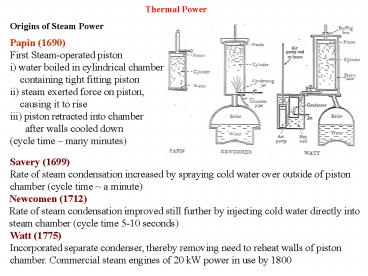
Origins of Steam Power Papin (1690) First
Steam-operated piston i) water boiled in
cylindrical chamber containing tight fitting
piston ii) steam exerted force on piston,
causing it to rise iii) piston retracted into
chamber after walls cooled down (cycle
time many minutes)
Savery (1699) Rate of steam condensation
increased by spraying cold water over outside of
piston chamber (cycle time a minute)
Newcomen (1712) Rate of steam condensation
improved still further by injecting cold water
directly into steam chamber (cycle time 5-10
seconds)
Watt (1775) Incorporated separate condenser,
thereby removing need to reheat walls of piston
chamber. Commercial steam engines of 20 kW power
in use by 1800
2
Thermal Power Stations
Note thermal includes fossil-fuel and nuclear
power Heat source is part of Steam
Cycle Thermodynamics of cycle independent of
nature of heat source
3
Phase diagram of water
4
Properties of Steam
T
Dryness fraction (quality) x
mvapour/(mvapour mwater) s (1 - x) swater
x svapour
s
Entropy/temperature diagram is best for power
station cycles Any TWO thermodynamic parameters
are sufficient to define state of fluid eg S,T or
P,H (Steam Tables)
5
Carnot Cycle (Ideal Cycle)
- Heat absorption at constant
- temperature, Ta (boiler) 1_2
- 2) Isentropic expansion _ work
- output (turbine) 2_3
- Heat rejection at constant
- temperature, Tb (condenser) 3_4
- Isentropic compression
- (pump)
4_1
Energy Conservation (1st Law of Thermodynamics)
Q12 W23 Q34 W41 0 (Note Q12
gt 0, W23 lt 0, Q34 lt 0, W41 gt 0)
Cycle efficiency, hc (Useful work out)/(Heat
input at Ta) ie hc ( W23 - W41)/ Q12 (Ta -
Tb)/ Ta 1 - Tb/ Ta (Note T measured in K
(absolute temperature) formal definition of
absolute temperature scale)
6
Practical difficulties in using a Carnot Cycle
- Boiler operates only in wet-steam regime
otherwise temperature - would rise when all the water has turned to
steam, violating - condition for Carnot Cycle
- _ turbine expands wet steam
- _ water droplets hit turbine blades (damage)
- Maximum temperature (Ta) is limited to 650 K
- _ efficiency of cycle is severely
constrained
- Compression of water/steam mixture is
thermodynamically - unstable (water _ droplets)
- _ very large volume compressor (expensive)
Rankine Cycle overcomes all these problems
7
Rankine Cycle
Step 1 a) Condense all the steam to water in the
condenser b) Pumping water to high pressure
requires small volume machine and little energy
- Step 2
- Use 3-stage boiler ( constant pressure)
- Economiser water heated at constant pressure
- Evaporator water/steam mixture heated at
constant pressure - Superheater dry steam heated at constant
pressure - Note that there is a small drop in pressure
through the boiler tube - in order to overcome frictional losses
8
Step 3 Expand dry steam through a turbine to
generate shaft power
In practice, water droplets still form in the
low pressure end of the turbine, so the steam is
reheated at various stages
9
Frictional losses across turbine blades vary like
u2 (FD½CDrAu2) ie very large for large u (near
speed of sound) Losses reduced significantly by
using many stages in series (50 stages)
The loss of kinetic energy at each stage is
small and turbulence is reduced
Other practical effects limiting efficiency
- Boiler tubes have finite thickness, so outer wall
temperature is higher - than water/steam temperature
- Metallurgical limit to temperature/pressure
difference boiler tubes - can withstand (creep/crack formation)
- Many pipes/tubes in flow circuit _ frictional
losses
d) Condenser is a vacuum chamber _ air leaks in
but can not condense, so air blanket
forms, preventing water vapour from condensing
on cold surface of condenser tubes
10
Efficiency of Rankine Cycle
Condenser at 30 C at a pressure of 0.04
bar Compressor increases pressure to 170
bar Three-stage boiler at 170 bar a)
economiser raises temperature to 352 C b)
evaporator at 352 C c) superheater raises
temperature to 600 C Adiabatic turbine
T p hf hg sf sg Water/Steam 30 0
.04 126 2566 0.436 8.452 Water/Steam 352 170 1690
2548 3.808 5.181 Dry Steam 600 170 3564 6.603
where hf and hg are the specific enthalpies and
sf and sg are the specific entropies of the fluid
and gas, respectively, in kJ/kg.
11
Adiabatic compression or expansion
Work done by the shaft Ws on the fluid
Adiabatic so Q 0
Total work W
First Law DU Q W
W Ws (p1v1 - p2v2) DU u2 - u1 Ws
(u2 - u1) - (p1v1 - p2v2) (u2 p2v2) -
(u1 p1v1) h2 - h1 In adiabatic
process work done equals change in enthalpy
Note sign convention
12
Specific enthalpy h u pv dh TdS Vdp
isobaric, constant pressure, dh du pdv
dQ isentropic Dh W Vdp
ii) 1_2 isentropic so h2 h1 W12 126
17 143 kJ/kg
iii) 2_3 isobaric so Q23 h3 h2 3564
- 143 3421 kJ/kg
- 3_4 isentropic so
- W34 h3 h4 and s3 s4
- s4 (1-x)sf4 xsg4
- s3 6.603 (1-x)0.436 8.452 x
- x 0.769
13
v) h4 (1-x)hf4 xhg4 h4 (1-x)126
2566 x x 0.769 h4 2002 kJ/kg
3_4 isentropic so W34 h3 h4 3564
2002 1562 kJ/kg
vi) h useful work/heat in (W14
W12)/Q23 (1562 17)/3421 0.452
45.2
vii) cf Carnot Cycle hc (T3 - T4)/T3
(873 - 303)/873 0.653 65.3
14
Combined Cycle Gas Turbine (CCGT) Stations
In recent years gas turbines and steam turbines
have been combined to increase the efficiency to
around 50-60 (upper temperature 1200 C)
- a) Heat generated by internal combustion rather
than - via a high temperature heat exchanger (boiler)
- b) No cooler required since exhaust gases vented
to - atmosphere
- _Plant much smaller. Work done by compressor is
- significant, though this is compensated by very
high - temperature 1200 C (Turbine blades ceramic
coated - and water cooled)
15
CCGT Station
air
Exhaust gas
Heat in
Boiler
Turbine
Compressor
compressed air
Turbine
Combustion Chamber
Gaseous fuel
w
Water Pump
Exhaust gas
Condenser
Cooling water
Heat out
Heat of exhaust gases used to raise steam for
steam turbine Many CCGTs have been built in the
UK in the 90s due to availability of cheap gas
and relaxation of governmental controls
16
660 MW Power Plant
Low pressure turbine, part of a 660 MW assembly
Stator for a 660 MW generator being assembled
17
Types of Fossil Fuel Power Stations
18
- Technical Solutions to Disposing of CO2
- Snowballs of dry ice
- 5 107 tonnes per ball 400m diameter (requires
power to refrigerate) - Underground storage
- In aquifiers, used gas/oil fields - huge
storage potential, but - possibility of spontaneous gas eruptions (1750
people killed by CO2 - eruption from volcanic lake in 1986)
- Deep ocean disposal
- Large hydrostatic pressure _ CO2 liquifies
- - long-term viability uncertain
- - effect on ocean deep-sea creatures uncertain
(affects food chain of - surface creatures
- Pump CO2 into lakes/breed algae
- Algae _ dried biomass _ alternative to fossil
fuel - (no net CO2 produced due to short recyling
period)
19
Carbon Dioxide Reduction
20
Nuclear Power
Historical Milestones
- Becquerel Fogging of
photographic plates near U salts - Einstein Special theory of
relativity- E mc2 - Rutherford Discovery of nucleus
- a-particle scattering - Bohr Quantum model of
H atom - Chadwick Discovery of neutron
- Bohr, Frenkel Liquid drop model of
nucleus
- 1938 Hahn, Strassmann Discovery of fission
- Joliot, von Halban Discovery of neutrons
produced in fission - Kowarski reactions
_possibility of chain reaction - Szilard, Wigner Advised Roosevelt of
feasibility of uranium - bomb
21
- Booth, Dunning, Start of projects to
separate isotopes of - Urey 235U and
238U - 1940 Anderson, Fermi Showed that 12C would
be a good moderator - 1940 Joliot, Dautry Transferred D2O
from Norway to UK - 1940 Seaborg Discovered
Plutonium - 1942 Groves Manhattan
Project started - Fermi First nuclear
reactor- demonstrated that - chain
reaction controllable - Bethe, Weisskopf Defined specification of
atomic bomb - Teller, Feynman (sub-critical
sphere surrounded by -
explosives _ compression _ criticality)
May 1945 Experimental uranium bomb
exploded July 1945 Experimental
plutonium bomb exploded Aug 1945
Hiroshima destroyed by U-bomb Nagasaki
destroyed by Pu-bomb
22
First self-sustaining chain reaction Fermi
December 1942 Chicago University Stadium
23
- UKAEA established in UK, CEA
established in France - Fast reactor programme started
- 1956 First prototype power station
(Calder Hall) gas cooled - 1956 Suez crisis _ oil shortage _
nuclear power stations - _ first commercial
reactors 1962 (Berkeley, Bradwell) - 1957 Pressurised Water Reactor
(PWR) developed for - nuclear submarines by the
USA - 1957 Windscale fire (Wigner energy
underestimated) - 1957 Campaign for Nuclear
Disarmament (CND) established - 1959 Dounreay fast reactor _
critical
1964 UK decide to build Advanced
Gas cooled Reactors (AGR) 1976
First AGRs commissioned (Hinckley B, Hunterston
B) 1979 Three Mile Island accident
(operator errors) 1986 Chernobyl
accident (design faults, operator errors,
no regulation 1991/2
Collapse of communism in E.Europe _ nuclear
cooperation (civil and
military) 1995 First PWR in UK
(Sizewell B)
24
Binding Energy of Nuclei
MeV
8
In fission A1 ? A2 A3 neutrons, where A2
and A3 are the final stable nuclei, the total
energy release ER is approximately ER A2b(A2)
? b(A1) A3b(A3) ? b(A1).
6
Fission
B/A
4
Fusion
2
0
Mass Number A
- Above mass 20 approximately constant binding
energy per nucleon - However more stable nuclei can be formed either
by - Fusion (combining 2 nuclei with low mass number
A) - Fission (breakup of large A nucleus into lower A
fragments plus - release of neutrons)
25
Basic Ideas Fission Reactors
? chain reaction
n 235U92 _ 141Ba56 92Kr36 3n
Change in mass, dm 3.6 10-28 kg Energy
released, E (dm)c2 (3 108)2 3.6
10-28 3.2
10-11 J cf chemical combustion C O2 _
CO2 E 7 10-19 J
Energy release from 1 uranium nucleus 5 107
carbon atoms 1 tonne of 235U 2.7
106 tonnes of coal U is 0.7 235U so 1 tonne U ?
20,000 tonnes of coal
26
- Naturally-occurring uranium consists of
- fissile isotope 235U
- stable isotope 238U
ratio 1/138 0.7
Not enough n to continue chain reaction with H2O
moderation _ enrichment necessary to increase
ratio 235U/238U _ 3
27
Fuel Enrichment
Enrichment is process of increasing proportion of
fissionable nuclei in natural uranium (0.7 235U)
Used for Manhattan project (1g/day) and by Iraq
before Gulf War
28
- Gaseous Diffusion
- Uranium ore converted to UF6 gas passed
through very thin porous - membranes. Light 235U molecule diffuses
faster than the heavier - 238U molecule. 1400 stages to achieve
3-5 235U/238U
- Ultracentrifuge
- Gaseous UF6 is rotated at high angular
velocity in a cascade of - centrifuges, causing partial separation
- Laser Separation
- Tuned lasers selectively ionise the lighter
isotope in UF6 vapour - Positive ion attracted to charged collector
plates still being - developed
29
Enrichment
30
Energy Released by Fission Process
Instantaneous Release (per fission)
MeV Fission products 168 _
heat Neutrons 5 g-rays 7 _ heat
Delayed Release (per fission)
MeV b-particles 8 _
heat g-rays 7 _ heat Antineutrinos
12 lost from reactor
31
Neutron Energy Distribution
On average, 2.44 neutrons are produced per
fission Average neutron energy is 2MeV
32
Macroscopic cross-sections for natural uranium
(St Snisti)
33
Factors affecting chain reaction
- For each thermal neutron absorbed, h effective
fast neutrons emitted - h lt n, mean number produced (n 2.42 for 235U),
because not all - neutrons absorbed by fuel cause fission. Nat U
(0.72 235U) h 1.33
2) Some fast neutrons cause fission before
slowing down which increases the number of
neutrons by the fast fission factor e
3) The probability that a neutron will avoid
resonance capture by 238U the resonance
escape probability p - depends on the moderator
4) The fraction of thermal neutrons that are
absorbed by the fuel in the core (fuel,
moderator, can) is called the thermal utilization
factor f
5) There are a fraction lf of fast neutrons and a
fraction lt of thermal neutrons that leak
out of the reactor
The neutron multiplication factor k is therefore
given by k hepf (1- lf) (1- lt) For
infinite core k? hepf Four factors
formula
34
Neutron Moderation
Moderator is a medium for reducing the kinetic
energy of neutrons from MeV to thermal level
without losing many in the resonant trap of 238U
M
m
For 180 deg scattering
neutron
nucleus
Es (M - m)/(M m)2Ei (A - 1)/(A 1)2Ei
Averaging, Es ½1 (A - 1)/(A 1)2Es
(A2 1)/(A 1)2Es
(Averaging over all angles gives the same
result) 1H 12C 238U A 1 12 238
Es/Ei 0.5 0.86 0.99
35
How many collisions required to reduce neutron
energy from 2 MeV to 1 eV ? (factor of 2 106)
Put (Es/Ei)n 1/(2.106) 5.10-7 eg 1H gives
n 21, 12C gives n 96
- Moderating Ratio, MR
- Good moderators require
- large selastic (sel)
- low scapture (sc)
- significant loss in KE per collision
- chemical stability (in hot, radioactive
environment) - Moderating ratio, MR (1- Es/Ei) sel/sc
H2O 62 D2O 4830 C 216
Reactor Control If the neutron flux increases to
a higher level than that needed for a stable
chain reaction, how can the reactor be
controlled, ie how can equilibrium be restored?
36
Lower control rods into reactor to absorb
excess neutrons Materials used 113Cd (sc
20,000 barns) 10B
(sc 4,000 barns) cross section is for thermal
neutrons (0.025 eV) sc(max) p(l /2p)2 2.6
107 barns (withdraw control rods if reactivity
gets too low)
In practice control would be virtually impossible
but for the existence of delayed
neutrons Delayed neutrons are released only after
the b-decay of a fission product Typically,
about 1 of neutrons produced by fission are
delayed by 10-20 seconds, which is enough time
for small adjustments in the position of the
control rods (automatically controlled)
37
Neutron Population Growth
- is number of neutrons emitted per neutron
absorbed - Because of losses the mean number is k, where k lt
h - k is the effective multiplication factor
If all neutrons were prompt the neutron
population would grow like dn/dt n(k-1)/t
nq/t where q(k-1) and t is the average neutron
lifetime in the reactor So n noexpqt/t eg
q 0.001, t 0.001 second gives n noexp(t),
so after 10 s n/no increases by a factor of
22,000
38
If q ltlt b, the effective generation time is the
average lifetime ta for the emitted neutrons
ta (1- b)t b(td t) btd t which for t
0.001 s is 0.06 s . The effective reactor
period T becomes T ta/qln2 80 s which gives
adequate time for mechanical control
39
Reactor Designs
Steam to turbine
Pressurised Water Reactor PWR
As a reactor is operated certain fission
fragments (notably xenon and samarium) are
produced with high neutron capture cross
sections As these reactor poisons build up the
multiplication factor k decreases
40
Safety Features in a PWR
- The control rods can be lowered fully in the
case of an emergency
- Should the pressure drop in the primary loop and
the water start to boil, the creation of bubbles
(voids) decreases the moderation and also the
absorption. The effect on the moderation is the
more significant and the chain reaction stops and
the reactor is no longer critical
- The moderation is also decreased if the core
temperature rises, as this increases the Doppler
broadening of the 238U resonances, which
decreases the resonance escape probability p
- A loss-of-coolant accident (LOCA) in which the
water in the primary loop is lost requires
additional emergency cooling to be available. The
outer containment vessel provides a final barrier
and worked successfully in the Three Mile Island
accident
41
Power Output of Nuclear Reactor
Reaction rate R (Neutron Flux)?(Cross-section)?(
Number of Nuclei) Flux f Neutrons m-2s-1
Number of Nuclei N Cross-section s
effective area, unit is barn 10-28 m2
Example Reactor core contains 104 kg of uranium
enriched to 2 in 235U. Cross-section for
neutron induced fission of 235U 579 barns. Flux
f 1018 m-2s-1. Calculate the power output.
Number of 235U nuclei 104(1000/238)(6
?1023)(0.02) 5.0?1026 R fsN
1018?579?10-28?5.0?1026 2.9?1019 s-1
Energy per fission 200 MeV 200?106?1.6?10-19
3.2?10-11 J So power output 3.2?10-11
?2.9?1019 0.93 GW.
42
Fast Breeder Reactors (FBR)
- Predicted fossil reserves 8.1022 J
- Fission reactors (thermal neutron) 4.1021 J
- Fast breeder reactors (fast neutrons) 2.1023 J
- fast breeder reactors are possible long-term
solution to worlds - energy needs (103 years) - 50 times fission
reactor energy reserve - Fission reactors consume 235U so lt 1 uranium
utilised - Fast breeder reactors have small core of highly
enriched fissile fuel - with no moderator. Emitted fast neutrons convert
surrounding 238U - to fissile 239Pu quicker than fuel consumed by
fast neutron induced - fission in core.
43
(No Transcript)
44
(No Transcript)
45
Pebble-Bed Nuclear Reactor
Newsweek April 8th-15th 2002
Uranium kernels coated with silicon carbide plus
graphite
46
World NUCLEAR POWER REACTORS 2003-04
47
Relative costs of electricity in the US
(2003) Costs of Electricity Generation
(2003) (25-year capital recovery, 85 lifetime
capacity factor) Source Cents/kWe-hr Nuclea
r 7.0 Coal
4.4 Gas 4.1 Nuclear Costs with
reduced Construction costs by 25
5.8 Construction time by 12 months 5.6 Cost of
capital coal and gas 4.7 With Carbon
Tax 50/tC 100/tC 200/tC Coal
5.6 6.8 9.2 Gas 4.6 5.1 6.2
48
Environmental Impact of Nuclear Power
Nuclear Fuel Cycle for typical reactor
600tU as enriched UF6
4200tU as enriched UF6
4200tU as enriched U3O8
Uranium mining, milling and concentration
Fuel fabrication as UO2
Enrichment to 3.5 235U
Conversion to UF6 (gas)
600tU as fresh UO2 fuel
24t HLW 100m3
Reprocessing and vitrification of HLW
Reactor Operation 1000 MW 30 years operation
200 109 kWh of electricity equivalent to 17.106
tonnes of oil
Final disposal- deep geological depository)
1
600tU in used fuel
Interim storage option (20 yrs )
600tU in used fuel 900m3 in containers
2
10,000 m3 waste (operating and decommissioning)
49
Categories of Nuclear Waste 1. LLW(Low Level
Waste) 89 of total volume Low radioactivity,
negligible long-lived activity (rags, tools,
filters, etc, from hospitals, research labs and
nuclear power stations 2. ILW (Intermediate
Level Waste) 11 of total volume Requires
sheilding, contains some long-lived activity
(resins, sludges, Fuel cladding) can be set in
concrete/bitumen 3. HLW (High Level Waste) 0.3
of total volume Highly active, heat generating,
long-lived activity requires vitrification and
long-term storage
National Waste Disposal Programmes France
400,000 m3 of short-lived waste in shallow land
burial at La Manche site Investigating sites for
deep disposal of long-lived waste (including
vitrified HLW) from 2015
50
Germany LLW and ILW in former salt
mine Investigations of Gorleben salt dome for
final disposal of vitrified HLW Japan LLW put
in shallow burial site (200,000m3 capacity). HLW
being vitrified and stored for 30-50 years until
suitable deep repository found UK Underground
repository for LLW/ILW at Sellafield. HHW
vitrified stored 50 years at Sellafield before
eventual disposal in deep repository USA Three
LLW sites. National HLW site Yucca Mountain
(Nevada)
- Outstanding Issues
- Deep repositories required to keep HLW intact
for 10,000 years - Geological stability and water ingress are
uncertain - Long-term stability of vitrified waste unknown
- Public unease- easy target for anti-nuclear
lobby - Moral issue- should we burden future generations
with our waste? - Counter argument they will also need to
dispose of nuclear waste, so - we are solving the technical problems for them.
Also danger from - not reducing CO2
51
Nuclear Power
Chernobyl
Recommended
