
Role of Pixel DB in PowerPoint PPT Presentation
1 / 19
Title: Role of Pixel DB in
1
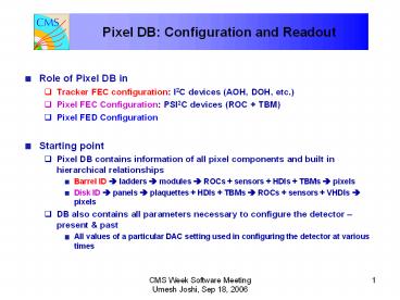
- Role of Pixel DB in
- Tracker FEC configuration I2C devices (AOH, DOH,
etc.) - Pixel FEC Configuration PSI2C devices (ROC
TBM) - Pixel FED Configuration
- Starting point
- Pixel DB contains information of all pixel
components and built in hierarchical
relationships - Barrel ID ? ladders ? modules ? ROCs sensors
HDIs TBMs ? pixels - Disk ID ? panels ? plaquettes HDIs TBMs ?
ROCs sensors VHDIs ? pixels - DB also contains all parameters necessary to
configure the detector present past - All values of a particular DAC setting used in
configuring the detector at various times
2
- Address all pixel devices using the names
specified in the Pixel Naming document - The DB will contain maps of a device name to all
quantities used to specify it in the detector - For example, a ROC on a forward pixel panel will
be mapped to its placement on a - Plaquette
- Panel
- Readout sequence
- Etc.
3
(No Transcript)
4
(No Transcript)
5
- Data to be downloaded by Tracker FEC
- Barrel
- 4 mFECs, each connected to a control network
- ID VME addresses
- 1 CCU / sector
- Identification node number
- 1 AOH 1 DOH motherboard / CCU
- 8 CCUs / control network (shell)
- Forward
- 4 mFECs, each connected to a control network
- 1 port card / 3 blades (1 disk)
- 1 CCU / octant (2 disks) ? 2 port cards
- 4 CCUs / control network (half-cylinder)
6
- AOH 2 modules (6 lasers) each with 4 internal
registers each - Base addresses 0X10 0X14
- DOH 1 DOH per Port Card 4 registers
- Base address 0X70
- PLL 1 PLL mounted on the Port Card (5 registers)
- Base address 0X20
- Delay25 1 mounted on Port Card (6 registers)
- Base address 0X30
- DCU 1 DCU mounted on the Port Card (8 registers)
- Base addresses 0X50
- 0X60
7
Base I2C Addresses (AOH motherboard) I2C
controller 1 (Layers 12) I2C
controller 3 (Layer 3) AOH-1A 0x08 AOH-5A
0x08 AOH-1B 0x0C AOH-5B 0x0C AOH-2A 0x10
AOH-6A 0x10 AOH-2B 0x14 AOH-6B 0x14 AOH-3A
0x18 AOH-3B 0x1C AOH-4A 0x20 AOH-4B
0x24 Base I2C addresses (DOH motherboard) DEL-1
0x60 PLL-1 0x40 PLL-3 0x40 DOH-1 0x70
DOH-3 0x70
8
- DB Access
- DB maintains relationships between all components
- Specification of a particular mFEC allows
identification of all connected components - Allows TrackerFecSupervisor to access all I2C
download parameters by simply specifying a
particular mFEC (control network) - Retrieve mFEC ID CCU ID I2C Controller ID
I2C register register value
9
(No Transcript)
10
(No Transcript)
11
- mFEC has two sets of optical links (four fibers
each) - Barrel Connect 2 DOH motherboards (1/ link set)
- Forward Connect 2 Port cards (1/link set)
- Optical link terminates at DOH motherboard (port
card) - Signals converted to electrical and fanned out to
modules (panels) - 1 hub per module (panel)
- Hub address 5 bits wide (max 32)
- 5 ports per hub
- Port address 3 bits
- Port 4 always occupied by TBM (TBM A TBM B)
- Ports 0 ? 3 for ROCs
12
- Barrel 4 ROCs per port
- Forward 1 plaquette per port
- ROC address 4 bits (PSI2C)
- Address starts from 0 and increases sequentially
in the order in which the token is passed. - Exception Barrel modules with dual TBM readout.
- Addresses of ROCs readout by TBM B start at 8
- TBM address is fixed 0XE0 (A) 0XF0 (B)
- Barrel each ROC on a module has a distinct
address - Forward each ROC on a plaquette has a distinct
address
13
- Information needed by PixelFecSupervisor to
address - Barrel ROC
- mFEC ID module ID ROC ID pixel ID
- Forward ROC
- mFEC ID panel ID ROC ID pixel ID
- Both cases
- mFEC ID TBM hub ID TBM port ID ROC ID
pixel (col, row) - DB has information on components connected to a
mFEC - By simply specifying an mFEC it is possible to
retrieve from DB all information necessary to
configure all components connected to it
14
- Design of the module (plaquette/panel) specifies
the order in which the token is passed - This is the order in which the ROCs are readout
- A FED identifies a ROC by its position in the
analog output (UB) - This ID has to be mapped to the ROC (e.g.
position on a module) in the DB - FED Configuration
- Decoding ? download associated address levels
(from DB) - Summary For a ROC we know the following (in
addition to others) - Placement on the wafer (history) serial number
- Placement on a module/plaquette (addressing)
- Placement on a module/panel
- Placement in a readout sequence
15
(No Transcript)
16
DISPLAY_NAME PANL_SER_NUM PLAQ_SER_NUM TBM_SER_NUM ROC_SER_NUM ROC_POS SNSR_SER_NUM
Pixel Panel P3R_001 P_2x3T_925_C XH4IN9T-41_2 XN4F4YT-15_1 0 925-2x3T
Pixel Panel P3R_001 P_2x3T_925_C XH4IN9T-41_2 XN4F4YT-15_3 1 925-2x3T
Pixel Panel P3R_001 P_2x3T_925_C XH4IN9T-41_2 XN4F4YT-52_1 2 925-2x3T
Pixel Panel P3R_001 P_2x3T_925_C XH4IN9T-41_2 XN4F4YT-44_0 3 925-2x3T
Pixel Panel P3R_001 P_2x3T_925_C XH4IN9T-41_2 XN4F4YT-34_0 4 925-2x3T
Pixel Panel P3R_001 P_2x3T_925_C XH4IN9T-41_2 XN4F4YT-24_0 5 925-2x3T
Pixel Panel P3R_001 P_2x4B_919_C XH4IN9T-41_2 XT4EF6T-59_3 0 919-2x4B
Pixel Panel P3R_001 P_2x4B_919_C XH4IN9T-41_2 XT4EF6T-35_2 1 919-2x4B
Pixel Panel P3R_001 P_2x4B_919_C XH4IN9T-41_2 XT4EF6T-54_0 2 919-2x4B
Pixel Panel P3R_001 P_2x4B_919_C XH4IN9T-41_2 XT4EF6T-53_3 3 919-2x4B
Pixel Panel P3R_001 P_2x4B_919_C XH4IN9T-41_2 XT4EF6T-45_0 4 919-2x4B
Pixel Panel P3R_001 P_2x4B_919_C XH4IN9T-41_2 XT4EF6T-2_0 5 919-2x4B
Pixel Panel P3R_001 P_2x4B_919_C XH4IN9T-41_2 XT4EF6T-2_1 6 919-2x4B
Pixel Panel P3R_001 P_2x4B_919_C XH4IN9T-41_2 XT4EF6T-53_1 7 919-2x4B
Pixel Panel P3R_001 P_2x5_925_C XH4IN9T-41_2 XN4F4YT-7_2 0 925-2x5
Pixel Panel P3R_001 P_2x5_925_C XH4IN9T-41_2 XN4F4YT-47_2 1 925-2x5
Pixel Panel P3R_001 P_2x5_925_C XH4IN9T-41_2 XN4F4YT-5_2 2 925-2x5
Pixel Panel P3R_001 P_2x5_925_C XH4IN9T-41_2 XN4F4YT-1_3 3 925-2x5
Pixel Panel P3R_001 P_2x5_925_C XH4IN9T-41_2 XN4F4YT-25_1 4 925-2x5
Pixel Panel P3R_001 P_2x5_925_C XH4IN9T-41_2 XN4F4YT-3_3 5 925-2x5
Pixel Panel P3R_001 P_2x5_925_C XH4IN9T-41_2 XN4F4YT-16_0 6 925-2x5
Pixel Panel P3R_001 P_2x5_925_C XH4IN9T-41_2 XN4F4YT-61_3 7 925-2x5
Pixel Panel P3R_001 P_2x5_925_C XH4IN9T-41_2 XN4F4YT-49_0 8 925-2x5
Pixel Panel P3R_001 P_2x5_925_C XH4IN9T-41_2 XN4F4YT-3_1 9 925-2x5
17
(No Transcript)
18
(No Transcript)
19
- mFEC has two sets of optical links (2 Port Cards)
- Optical link terminates at Port Card
- signals converted to electrical and fanned out to
6 adapter cards - Signal ends at a hub (5 bit address)
- ?6 hubs connected to a mFEC (link)
- Each hub has 5 ports
- Port 4 always occupied by TBM (2 TBMs, A B)
- Ports 0 ? 3 for ROCs
- Forward 1 Plaquette connected to a port
- Barrel 4 ROCs per port
Recommended
