
Introduction to Fatigue PowerPoint PPT Presentation
1 / 15
Title: Introduction to Fatigue
1
Introduction to Fatigue
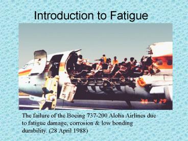
The failure of the Boeing 737-200 Aloha Airlines
due to fatigue damage, corrosion low bonding
durability. (28 April 1988)
2
Overview of Fatigue
- Many different mechanical failure modes exist in
all fields of engineering. - These failures can occur in simple, complex,
inexpensive, or expensive - components or structures.
- Failure due to fatigue, i.e., repeated loading,
is multidisciplinary and is - the most common cause of mechanical failure.
- Even though the number of mechanical failures
compared - to successes is minimal, the cost in lives,
injuries, and dollars is too large. - Proper fatigue design can reduce these
undesirable losses. - Proper fatigue design includes synthesis,
analysis, and testing. - The closer the simulated analysis and testing are
to - the real product and its usage, the greater
confidence - in the engineering results.
3
FATIGUE ANALYSIS NEEDS
- The principles of fatigue behaviour and
fatigue design have been developed, used, and
tested by engineers and scientists in all
disciplines and in many countries. - The current capability of computers and
simulated testing has a pronounced influence on
the efficiency and quality of today's fatigue
design procedures. - However, in proper fatigue design, both
computer synthesis and analysis must be
integrated with proper simulated and field
testing, along with continued evaluation of
product usage and maintenance, including
non-destructive inspection.
4
Tips in Design for Fatigue
- 1. Do recognize that fatigue failures are the
most common cause of mechanical failure in
components, vehicles, and structures and that
these failures occur in all fields of
engineering. - 2. Do recognize that proper fatigue design
methods exist and must he incorporated into the
overall design process when cyclic loadings are
involved. - 3. Do not rely on safety factors in attempting to
overcome poor design procedures. - 4. Do consider that good fatigue design, with or
without computer-aided design, incorporates
synthesis, analysis, and testing. - 5. Do consider that fatigue durability testing
should be used as a design verification tool
rather than as a design development tool. - 6. Do not overlook the additive or synergistic
effects of load, environment, geometry, residual
stress, time, and material microstructure
5
STRATEGIES IN FATIGUE DESIGN
- Fatigue design methods have many similarities
but also differences. - The differences exist because a component,
structure, or vehicle may be safety critical or
non-safety critical, simple or complex, expensive
or inexpensive, and failures may be a nuisance or
catastrophic. - The product may be a modification of a current
model or a new product. Significant
computer-aided engineering (CAE) and
computer-aided manufacturing, CAM) capabilities
may or may not be available to the design
engineer.
6
FLOW CHART FOR STRATEGIES IN FATIGUE DESIGN
Fatigue design flow chart originated by H. S.
Reemsnyder from Bethlehem Steel Corp. and
slightly modified by H. 0. Fuchs, It was created
for use by the Society of Automotive Engineers
Fatigue Design and Evaluation (SAEFDE) Committee
University of Iowa's annual short course on
Fatigue Concepts in Design.
7
Choosing the fatigue life model
- Choosing the fatigue life model is a significant
decision. - Currently four such models exist for design
engineers. These are - The nominal stress-life (S-N) model, first
formulated - between the 1850s and 1870s.
- 2. The local strain-life (?-N) model, first
formulated in the 1960s. - 3. The fatigue crack growth (da/dN-?K) model,
first formulated in the 1960s. - 4. The two-stage model, which consists of
combining models 2 and 3 - to incorporate both macroscopic fatigue crack
formation (nucleation) - and fatigue crack growth.
8
Purposes of Design
- 1. Designing a device, perhaps a special bending
tool or a test rig, to be used in the plant where
it was designed. It is called by an "in-house
tool." - 2. Changing an existing product by making it
larger or smaller than previously, using a
different material or different shapes, perhaps a
linkage and coil spring in place of a leaf
spring. It is called by a "new model." - 3. Setting up a major project that is quite
different from past practice. A spacecraft or an
ocean drilling rig or a new type of tree
harvester is example. It is called by a "new
product." - 4. Designing a highway bridge or a steam boiler.
The expected loads, acceptable methods of
analysis, and permissible stresses are specified
by the customer or by a code authority. It is
called by "design to code."
9
Tips in Design Related to Crack Initiation
- 1. Do recognize that fatigue is a localized,
progressive, and permanent behaviour involving
the nucleation and growth of cracks to final,
usually sudden fracture. - 2. Do recognize that fatigue cracks nucleate
primarily on planes of maximum shear and usually
grow on the plane of maximum tensile stress. - 3. Do examine fracture surfaces as part of a
post-failure analysis, since substantial
information concerning the cause of the fracture
can be gained. The examination can involve a
small magnifying glass or greater magnification
up to that of the electron microscope. - Do not put fracture surfaces back together again
to see if they fit or allow corrosive
environments (including rain and moisture from
fingers) to reach the fracture surface.
10
Tips in Design Related to Crack Initiation (cont.)
- 5. Do consider that stress-strain behaviour at
notches or cracks under repeated loading may not
be the same as that observed under monotonic
tensile or compressive loading. - 6. Do take into consideration that your product
will very likely contain cracks during its design
lifetime. - 7. Do recognize that most fatigue cracks nucleate
at the surface, and therefore that surface and
manufacturing effects are extremely important. - 8. Do not assume that a metal that has good
resistance to crack nucleation also has good
resistance to crack growth and vice versa.
11
Fatigue Loading
Constant amplitude cyclic loading.
Schematic ground-air-ground flight spectrum.
12
Tips in Design for Fatigue Test and the
Stress-Life (S-N) Approach
- 1. Do consider the wide range of test systems and
specimens available for fatigue testing. Tests
can range from those performed on small, highly
polished specimens for material characterization
to full-scale durability tests of large
structures. - 2. Do not neglect to refer to ASTM, ISO, or
similar standards on fatigue testing and data
reduction techniques. - 3. Do consider that the fully reversed fatigue
strength, Sp at 106 to 108 cycles for components
can vary from about 1 to 70 percent of the
ultimate tensile strength and that the engineer
can substantially influence this value by proper
design and manufacturing decisions. - 4. Do note that cleaner metals, and generally
smaller grain size for ambient temperature, have
better fatigue resistance.
13
Tips in Design for Fatigue Test and the
Stress-Life (S-N) Approach (cont.)
- 5. Do recognize that frequency effects are
generally small only when corrosion, temperature,
or other aggressive environmental effects are
absent. - 6. Do consider that surface finish can have a
substantial influence on fatigue resistance,
particularly at longer lives. - 7. Do not neglect the advantages of compressive
mean or compressive residual stresses in
improving fatigue life and the detrimental effect
of tensile mean or tensile residual stresses in
decreasing fatigue life, and that models are
available to account for these effects. - 8. Do attempt to use actual fatigue data in
design however, if this is not possible or
reasonable, approximate estimates of median
fatigue behaviour can be made.
14
Tips in Design for the Strain-Life (?-N) Approach
- 1. Do consider that inelastic stress-strain
behaviour under repeated loading is not the same
as that determined under monotonic tensile or
compressive loading. Under repeated loading the
difference between materials is less than that
under monotonic loading. - 2. Do not ignore the role of material hardening
or softening in cyclic loading applications.
Using a monotonic stress-strain curve of a cyclic
softening material in a cyclic loading
application can significantly underestimate the
extent of plastic deformation present. - 3. Do consider the importance of material
ductility on low-cycle or plastic strain
dominated fatigue resistance and the importance
of material strength on the high-cycle or elastic
strain dominated fatigue resistance. - 4. Do recognize that strain-life fatigue data of
smooth uni-axial specimens are based on cycles to
failure, where failure represents the formation
of cracks on the order of 1 mm in depth, which
may or may not have caused fracture. - 5. Do recognize that mean strains generally
affect fatigue resistance only if they produce a
non-relaxing mean stress. The greatest effect of
mean stress is in the high-cycle fatigue regime.
15
End
Recommended
