
Chapter 3 Photogrammetry PowerPoint PPT Presentation
1 / 155
Title: Chapter 3 Photogrammetry
1
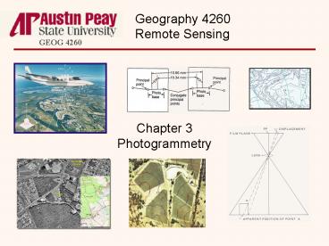
Chapter 3Photogrammetry
Geography 4260Remote Sensing
GEOG 4260
2
Elements ofPhotographic Systems
GEOG 4260
- Photogrammetry is the science and technology of
obtaining spatial measurements and geometrically
reliable derived products such as maps from
photographs or digital imagery. - Photogrammetry was developed around hardcopy
photographic negatives and prints, but has been
extended to digital or softcopy photogrammetry.
3
Elements ofPhotographic Systems
GEOG 4260
- A primary application of photogrammetry is the
generation of topographic maps from aerial
photography, but many other applications are
possible including the production of
geometrically accurate orthophotographs from
aerial photos and satellite imagery.
4
Elements ofPhotographic Systems
GEOG 4260
- Photogrammetry includes
- Determining image scale and making measurements
of distances from images, - Making area measurements from images,
- Quantifying the effects of relief displacement
on vertical aerial images, - Determination of object heights from image
relief displacement measurements, - Determination of object heights and terrain
elevations by measurements of image parallax
5
Elements ofPhotographic Systems
GEOG 4260
- Use of ground control points,
- Mapping from aerial images, and
- Flight mission planning necessary to obtain
cost-effective quality imagery.
6
Elements ofPhotographic Systems
GEOG 4260
- The use of the term images instead of
photographs is intentional. Although
photogrammetry was developed around aerial
photography, the techniques are applicable to
scanned photos and other forms of digital
imagery. - The notes on the remainder of this section
generally refer to photographs, but are equally
applicable to images of all types.
7
Elements ofPhotographic Systems
GEOG 4260
- Type of Aerial Photographs
8
Elements ofPhotographic Systems
GEOG 4260
- Aerial photos fall into two basic categories
- Vertical aerial photos, and
- Oblique aerial photos which include the
subcategories of - Low oblique, and
- High oblique.
9
Elements ofPhotographic Systems
GEOG 4260
- Oblique photos are generally less suited for
photogrammetric purposes than vertical air photos
because keeping the lens axis as vertical as
possible minimizes the geometric distortions that
are found in all aerial photos. - Although keeping the lens axis exactly vertical
is impossible, photos acquired when the axis is
less than 3 from the vertical are considered
vertical air photos and are suitable for
photogrammetric purposes.
10
Elements ofPhotographic Systems
GEOG 4260
- Acquiring Vertical Air Photos
11
Elements ofPhotographic Systems
GEOG 4260
- Vertical air photos are acquired along generally
straight flight lines or flight strips over the
ground surface. - The line on the ground surface directly below the
aircrafts path is the nadir line. If the lens
axis of the camera is perfectly vertical, the
principal point on a photograph would be
coincident with the nadir point. However, this is
generally not the case due to aircraft tilt and
pitch.
12
Elements ofPhotographic Systems
GEOG 4260
- Air photos are acquired at intervals along the
flight line, normally with about 55 to 65 percent
endlap between every adjacent pair of photos.
13
Elements ofPhotographic Systems
GEOG 4260
- Adjacent flight lines are arranged so that there
is also about 30 percent sidelap.
14
Elements ofPhotographic Systems
GEOG 4260
- Complete stereo coverage requires at least 50
endlap and that the photos in adjacent flight
lines at least abut one another.
15
Elements ofPhotographic Systems
GEOG 4260
- The larger percentages are used to ensure stereo
coverage and to allow features in the area of
sidelap to be shown optimally.
16
Elements ofPhotographic Systems
GEOG 4260
- Each adjacent pair of images along a flight line
forms a stereopair. The objects seen in the
endlap area of a stereopair are viewed from
different angles at the moments of exposure.
17
Elements ofPhotographic Systems
GEOG 4260
- When stereopairs are viewed through a
stereoscope, the viewer sees a three-dimensional
stereomodel of within the area of overlap.
18
Elements ofPhotographic Systems
GEOG 4260
- Using aerial stereopairs allows us greatly
exaggerate the stereo effect by effectively
separating our eyes by the air distance between
exposure.
19
Elements ofPhotographic Systems
GEOG 4260
- The ground distance between adjacent photo
stations is referred to as the air base. - The ratio of air base to flying height determines
the amount of vertical exaggeration seen in the
stereomodel.
20
Elements ofPhotographic Systems
GEOG 4260
- How can vertical exaggeration be increased?
- How can it be decreased?
21
Elements ofPhotographic Systems
GEOG 4260
- The Geometry of Vertical Air Photos
22
Elements ofPhotographic Systems
GEOG 4260
- Aerial cameras image the ground surface on a flat
plane that is above the lens at a distance equal
to the focal length of the lens (f). - The focal plane is perpendicular to the lens axis.
23
Elements ofPhotographic Systems
GEOG 4260
- The lens axis is oriented with 3 of the nadir
point which is where a vertical line extending
from the center of the lens system intersects the
ground surface.
24
Elements ofPhotographic Systems
GEOG 4260
- The intersection of the lens axis with the ground
surface defines the location of the principal
point of the photograph.
25
Elements ofPhotographic Systems
GEOG 4260
- The ground position of this point in the image is
defined as the ground principal point. - It is rarely exactly coincident with the nadir
point because of aircraft tilt.
26
Elements ofPhotographic Systems
GEOG 4260
- Light rays from objects on the ground pass
through the lens and focus an image of the ground
surface on the film plane.
27
Elements ofPhotographic Systems
GEOG 4260
- Each part of the scene is exposed to light
collected through the whole aperture, not just
through the center of the lens.
28
Elements ofPhotographic Systems
GEOG 4260
- The second plane shown below the lens is the
print plane.
29
Elements ofPhotographic Systems
GEOG 4260
- Straight lines drawn from objects on the ground
surface through the center of the lens pass
through the print plane and determine the
positions of objects in the negative used to
produce the print.
30
Elements ofPhotographic Systems
GEOG 4260
- Because most positive prints used for
photogrammetry are contact prints, the print
plane lies below the center of the lens at a
distance equal to the focal length of the lens.
31
Elements ofPhotographic Systems
GEOG 4260
- A Cartesian coordinate system can be defined for
a positive print by connecting opposite fiducial
marks with straight lines.
32
Elements ofPhotographic Systems
GEOG 4260
- The x axis of the coordinate system is
arbitrarily assigned to the fiducial line most
nearly parallel to the flight line, and the
origin of the coordinate system is located at the
principal point of the photo.
33
Elements ofPhotographic Systems
GEOG 4260
- X coordinates increase in the direction of flight
and y coordinates increase 90 to the left
(counterclockwise) of the x axis.
34
Elements ofPhotographic Systems
GEOG 4260
- Once the coordinate system is defined, the
location of any point in the image can be
specified by its x,y coordinate pair.
35
Elements ofPhotographic Systems
GEOG 4260
- In softcopy photogrammetry, the row and column
positions of objects can be converted into
photocoordinates through computer conversion
algorithms, most commonly an affine coordinate
transformation. - This process is similar to fitting a digitized
map into a mapping coordinate system with a GIS.
36
Elements ofPhotographic Systems
GEOG 4260
- Photographic Scale
37
Elements ofPhotographic Systems
GEOG 4260
- Photographic scale is the ratio of a distance in
an aerial photo to the same distance on the
ground surface using the same units of
measurements - S photo scale photo distance / ground
distance
38
Elements ofPhotographic Systems
GEOG 4260
- Photographic scale is usually expressed as a
representative fraction by dividing both the
numerator and the denominator of the scale
expression by the numerator of the expression. - This reduces the numerator to 1 and the result
is written as a ratio, e.g. 110,843.
39
Elements ofPhotographic Systems
GEOG 4260
- What is the local scale of an aerial photography
if the measured distance between two road
intersections that are known to be one mile apart
is 3.52 inches? - If the photo distance between a water tower and
one of these road intersections is 0.25 inches,
how many feet is the tower from the intersection?
40
Elements ofPhotographic Systems
GEOG 4260
- Because the original measurements are in the same
units, the scale is dimensionless. - This makes it possible to determine ground
distances from photo distances in whatever units
the photogrammetrist chooses.
41
Elements ofPhotographic Systems
GEOG 4260
- Photo scales determined by comparing photo
distances to ground distances are strictly
applicable only between the pairs of points used
for the measurements. - Photo scale commonly varies widely even along a
line between two points. Therefore, it should be
determined using known points located as close as
possible to the end points of the distances we
wish to estimate.
42
Elements ofPhotographic Systems
GEOG 4260
- Photo scale can also be determined over areas of
flat terrain because it is also equal to the
ratio between lens focal length (f) and flying
height above the terrain (H) - Scale f/H
- H is easily determined by subtracting the
terrain elevation (h) from the aircrafts
altitude (H).
43
Elements ofPhotographic Systems
GEOG 4260
- The scale equation on the preceding slide is
derived from the geometric relationships shown in
this diagram.
44
Elements ofPhotographic Systems
GEOG 4260
- What would be the nominal scale of photography
acquired with a 6 lens over uniform terrain at
an elevation of 880 above sea level is photos
are acquired from an aircraft altitude of 6,080? - What scale would result if a 3.5 lens was used
instead? - Which of these lenses would produce the larger
scale imagery?
45
Elements ofPhotographic Systems
GEOG 4260
- We can conclude from the relationship between
scale and flying height above the terrain that
variations in terrain elevation produce spatial
variations in the scale of a photograph of the
terrain. - Only absolutely vertical air photographs over
absolutely flat terrain have uniform scales
across their extents. Even tilts less than the
nominal 3 tilt allowed for vertical air photos
produce measurable scale variations.
46
Elements ofPhotographic Systems
GEOG 4260
- The spatial variations in the scale produced by
variations in terrain elevations produce
geometric distortions in aerial photographs that
are not present in maps.
47
Elements ofPhotographic Systems
GEOG 4260
- Features shown on maps that have little or no
scale distortion are in their correct planimetric
positions relative to one another. - An aerial photograph, however, distorts both the
distances and the directions between features.
48
Elements ofPhotographic Systems
GEOG 4260
- These distortions in aerial photographs are a
result of the fact that aerial photographs are
perspective projections while maps are
orthographic projections.
49
Elements ofPhotographic Systems
GEOG 4260
- In an orthographic projection, features are
projected from the Earths surface onto the
mapping surface at 90 angles.
50
Elements ofPhotographic Systems
GEOG 4260
- In a perspective projection, features are
projected from the Earths surface onto the
mapping surface at angles that converge on a
point, i.e. the center of the cameras lens
system.
51
Elements ofPhotographic Systems
GEOG 4260
- Perspective projection causes objects that are
closer to the camera to be larger and to be
displaced radially outward from the principal
point of the image. - This relief displacement affects the positions of
terrain features, but it also causes the vertical
objects to lean outward from the center of the
image.
52
Elements ofPhotographic Systems
GEOG 4260
- Relief displacement is most pronounced on low
altitude, wide angle images that include tall
objects near their edges.
53
Elements ofPhotographic Systems
GEOG 4260
- This image is a reduced resolution version of the
original. - Click on the image to view a higher resolution
version.
54
Elements ofPhotographic Systems
GEOG 4260
- Measuring Areas on Aerial Photographs
55
Elements ofPhotographic Systems
GEOG 4260
- If the distortions introduced by relief
displacement and camera tilt are small enough to
be ignored, ground distances can be measured on
an aerial photograph of known scale. - It is also possible to measure the size of areal
units from the photo if these distortions are
negligible.
56
Elements ofPhotographic Systems
GEOG 4260
- The areas of regular geometric shapes are most
easily measured from areal photos because linear
measurements of the dimensions of the features
can be converted to areal measurements through
simply geometry.
57
Elements ofPhotographic Systems
GEOG 4260
- Irregular shapes are more difficult to measure,
but a variety of tools are available.
58
Elements ofPhotographic Systems
GEOG 4260
- Most simply, a transparent square grid or dot
grid can be laid down over the photo. - The number of grid cells or dots falling within
the area being measured is converted to an area
through a knowledge of the scale relationships.
59
Elements ofPhotographic Systems
GEOG 4260
- If more precise measurements of many features are
needed, it is more convenient to use a coordinate
digitizer to outline each area and let an
image-processing program or GIS calculate the
area of each feature.
60
Elements ofPhotographic Systems
GEOG 4260
- The Geometry of Relief Displacement
61
Elements ofPhotographic Systems
GEOG 4260
- Figure 3.13 illustrates the geometric components
of relief displacement and leads to a method to
determine the heights of objects from
measurements of relief displacement on single
aerial photographs.
62
Elements ofPhotographic Systems
GEOG 4260
- The lower plane is a horizontal datum which
intersects the base of the feature whose height
is to be determined. - The upper plane represents a vertical air photo
of the feature.
63
Elements ofPhotographic Systems
GEOG 4260
- The photo was taken from photo station L at
height H above the datum plane. - The tower is height h above the datum plane.
64
Elements ofPhotographic Systems
GEOG 4260
- The top of the tower at point A is imaged at
point a having been radially displaced from its
true planimetric position which is coincident
with its base at point A.
65
Elements ofPhotographic Systems
GEOG 4260
- The photo displace-ment (d) can be measured from
the photo. - The distance from the principal point to the top
of the tower (r) can also be measured from the
photo.
66
Elements ofPhotographic Systems
GEOG 4260
- Both d and r can be projected to datum from the
photo to determine equivalent ground distances.
67
Elements ofPhotographic Systems
GEOG 4260
- Because triangles AAA and LOA are similar
triangles, the ratios of their vertical and
horizontal lengths are identical - D/h R/H
68
Elements ofPhotographic Systems
GEOG 4260
- Using photo distances instead of ground distances
allows us to express the same relationship as - d/h r/H
69
Elements ofPhotographic Systems
GEOG 4260
- Rearranging the terms of d/h r/H to solve for d
yields - d rh/H
70
Elements ofPhotographic Systems
GEOG 4260
- d rh/H
- This equation indicates that relief displacement
is directly proportional to the height of the
tower and the distance from the ground principal
point for a given flying height.
71
Elements ofPhotographic Systems
GEOG 4260
- Determining Object Heights from Relief
Displacement
72
Elements ofPhotographic Systems
GEOG 4260
- Solving d rh/H for h yields an equation that
can be used to measure the height of an object
from a single vertical air photo if we know the
flying height of the aircraft above the base of
the object - h dH/r
73
Elements ofPhotographic Systems
GEOG 4260
- This equation (h dH/r) requires that we know
the flying height of the aircraft above the base
of the object (or can determine it), but the
other two variables are easily measured on the
photo.
74
Elements ofPhotographic Systems
GEOG 4260
- This accuracy of the method depends on the
assumptions that were used to derive it - The lens axis must be truly vertical,
- The aircraft altitude must be precisely known,
- The terrain elevation at the base of the object
must be precisely known, - The objects base and top must both be clearly
visible, and - The position of the photos principal point must
be accurately determined.
75
Elements ofPhotographic Systems
GEOG 4260
- If these assumptions are true, then very accurate
height measurements are possible from single air
photos. - However, significant camera tilt at the moment of
exposure or imprecise values for any of the
required measurements introduce errors that
produce imprecise results.
76
Elements ofPhotographic Systems
GEOG 4260
- Image Parallax
77
Elements ofPhotographic Systems
GEOG 4260
- If stereo images are available, then the parallax
that was introduced by viewing objects from two
different locations can be used to determine both
object heights and the locations of objects in a
ground coordinate system.
78
Elements ofPhotographic Systems
GEOG 4260
- Figure 3.15 illustrates the effects of aircraft
movement on the positions of objects that are
visible in both photos of a stereopair. - Both the absolute and relative photo positions of
points A and B are affected by parallax.
79
Elements ofPhotographic Systems
GEOG 4260
- However, parallax displace-ment occurs only
parallel to the line of flight. - Although the line of flight normally lies close
to the x-axis formed by connecting on pair of a
photos fiducial marks, it is usually not
coincident.
80
Elements ofPhotographic Systems
GEOG 4260
- The lack of coincident results primarily from the
fact that any crosswind forces the pilot to turn
the nose of the airplane slightly into the wind
to maintain a given track over the ground, but
imprecise navigation can also contribute to
variations in the airplanes path over the ground.
81
Elements ofPhotographic Systems
GEOG 4260
- The actual path of the aircraft, however, can be
located in a photograph that is part of a
stereopair if the photo location of the
stereopairs other component can be identified in
the photo.
82
Elements ofPhotographic Systems
GEOG 4260
- The actual flight paths determined by locating
the conjugate principal point in both photographs
can be used to define the x axis of a Cartesian
coordinate system which can then be used to
measure parallax (which is parallel to the
direction of this axis).
83
Elements ofPhotographic Systems
GEOG 4260
- A points parallax is expressed as
- pa xa xa
- pa parallax of point A,
- xa x coordinate of a on the left photo, and
- xa x coordinate of a on the right photo.
84
Elements ofPhotographic Systems
GEOG 4260
- Notice that xa has a negative value in this
situation. - The signs of coordinates must be used correctly
to avoid errors when these values are used later
to determine ground coordinates and elevations.
85
Elements ofPhotographic Systems
GEOG 4260
- One additional variable must be known to make use
geometric relationships show in this diagram,
i.e. the air base (B) which is the distance that
separates the two exposure stations.
86
Elements ofPhotographic Systems
GEOG 4260
- B can be determined from GPS positions obtained
at the time of exposure, or it can be estimated
as the average distance between the principal
point and the conjugated point of each photo in
the stereopair times the average scale factor of
the photos.
87
Elements ofPhotographic Systems
GEOG 4260
- The relationships shown in this diagram can be
used to along with the value of B to derive two
important equations known as the parallax
equations - XA B(xa/pa)
- and
- YA B(ya/pa)
88
Elements ofPhotographic Systems
GEOG 4260
- The parallax equations allow us to calculate x,y
coordinate positions in a map coordinate system
from measurements made on stereopairs. - XA B(xa/pa)
- and
- YA B(ya/pa)
89
Elements ofPhotographic Systems
GEOG 4260
- Making Parallax Measurements
90
Elements ofPhotographic Systems
GEOG 4260
- Parallax displacement results in the apparent
positions of objects being displaced parallel to
the flight line and proportionate to the
elevation. This section deals with measuring the
total amount of displacement.
91
Elements ofPhotographic Systems
GEOG 4260
- Although parallax measurements can be made
directly from the photographs by laying out the
flightline coordinate system and carefully
measuring distances with a finely-divided scale,
it is necessary to determine the x-coordinate of
each position separately and then take their
algebraic difference. - There are other methods available to measure
parallel that greatly simplify the task.
92
Elements ofPhotographic Systems
GEOG 4260
- One method is accomplished by taping the two
photographs of a stereopair to a table in such a
way that the flight lines of the photos are
coincident.
93
Elements ofPhotographic Systems
GEOG 4260
- Under these circumstances x x is equal to D
d. Because D is fixed, it is then only necessary
to measure d to determine p.
94
Elements ofPhotographic Systems
GEOG 4260
- Parallax measurements can be made with any linear
measuring device, but a parallax bar is
specifically designed to make very precise
measurements of parallax.
95
Elements ofPhotographic Systems
GEOG 4260
- A parallax bar is a finely-calibrated scale with
a vernier scale that allows very precise
measurements of the distances separating objects
on stereopairs.
96
Elements ofPhotographic Systems
GEOG 4260
- Various other devices based on this principal
facilitate this process by providing a stereo
view, magnification, and a floating mark. - A floating mark is line that appears to intersect
the surface of a stereo model or spot of light
that appears to hover above, below, or on the
surface at the point whose parallax is to be
determined.
97
Elements ofPhotographic Systems
GEOG 4260
- This diagram illustrates the stereoscopic
principals involved.
98
Elements ofPhotographic Systems
GEOG 4260
- After the images are positioned and D has been
determined, the user adjusts the apparent
position of the floating mark so that it
intersects or lies precisely on the surface at
the point in question. - The user can then read the points parallax from
a finely-calibrated scale or a digital readout.
99
Elements ofPhotographic Systems
GEOG 4260
- A parallax wedge is another tool designed to be
used with a stereoscope after the images have
been aligned.
100
Elements ofPhotographic Systems
GEOG 4260
- Under a stereoscope, the pairs of converging
lines on the parallax wedge appear as a single
sloping line passing through the surface of the
stereomodel at the location of the point whose
parallax is to be determined when the wedge is
properly positioned.
101
Elements ofPhotographic Systems
GEOG 4260
- The millimeter scales next to each pair of
converging lines appear as a single scale when
the photos are positioned under the stereoscope
as described earlier. - This allows the user to read a value where the
line appears to intersect the surface.
102
Elements ofPhotographic Systems
GEOG 4260
- The difference between values read at the top and
bottom of the same stereoscopic object is the
parallax of the object in millimeters. - The parallax equations can then be used to
determine the location and height of the object.
103
Elements ofPhotographic Systems
GEOG 4260
- This particular parallax wedge also includes
linear scales along the side, a protractor along
the bottom edge, and a square-dot grid above the
protractor. - At a retail price of 11.50, you might also
expect it to be gold plated.
104
Elements ofPhotographic Systems
GEOG 4260
- Parallax measurements can also be taken from
digital images using softcopy photogrammetric
techniques. - These techniques have the advantage that a
computer can compare the pixels within a small
area to maximize the correlation between pixel
values within the area and precisely determine
the parallax of the central pixel.
105
Elements ofPhotographic Systems
GEOG 4260
- They also have the advantage that a computer
solve a set of collinearity equations to
compensate for variations in aircraft altitude,
pitch, bank and yaw at the moment of exposure for
each photo. - This allows the software to recreate the geometry
of each photosite at the moment of exposure and
compensate for factors that are difficult (but
not impossible) to compensate for using manual
techniques.
106
Elements ofPhotographic Systems
GEOG 4260
- Ground Control
107
Elements ofPhotographic Systems
GEOG 4260
- Ground control points are one type of reference
data. - Ground control points are locations on the ground
surface whose coordinates are known in a mapping
coordinate system (or whose coordinates can be
determined) and whose location within an aerial
photograph can be precisely determined.
108
Elements ofPhotographic Systems
GEOG 4260
- Ground control points can include natural or
constructed features such as stream junctions or
the centers of road intersections, or they can be
permanent survey markers or other surveyed points
whose position is marked during photo acquisition
by painted targets or fabric materials that
contrast with the background around them.
109
Elements ofPhotographic Systems
GEOG 4260
- Because ground control points can be located in
both the ground coordinate system and the photo
coordinate system, they allow other points seen
only in an air photo stereo model to be assigned
coordinates in the ground coordinate system. - Ground control points can be horizontal control
points, vertical control points, or both.
110
Elements ofPhotographic Systems
GEOG 4260
- Although it is possible to locate and mark
surveyed control points prior to an aerial
photography mission, previously surveyed points
are few and far between in many areas. - Therefore, additional points, now including GPS
control points, are often established and marked
to increase the density of well-defined control
points.
111
Elements ofPhotographic Systems
GEOG 4260
- Virtually all photogrammetric techniques rely on
accurate ground control. Therefore, identifying
and marking control points prior to flight is a
critical stage in flight planning. - It does no good to locate the ground position of
a flight line on an aerial photo or on the ground
unless the ground coordinates of the end points
of the line can be accurately determined.
112
Elements ofPhotographic Systems
GEOG 4260
- However, it is also possible to identify points
in existing photos that can be located on the
ground and to determine the locations of those by
GPS or other survey techniques. - Establishing ground control after the flight
mission avoids the possibility that a previously
marked ground control point cant be easily
located in one or more of the photographs.
113
Elements ofPhotographic Systems
GEOG 4260
- Methods to simplify ground control by using GPS
receivers to simultaneously acquire data at a
single well-defined control point and onboard the
aircraft are currently being tested. - These methods require that the aircraft attitude
at the moment of each exposure be known in
addition to its three-dimensional location.
However, that data can be acquired with an
inertial measurement unit (IMU).
114
Elements ofPhotographic Systems
GEOG 4260
- An inertial measurement unit is an
electro-mechanical device that simultaneously
detects and records changes in acceleration and
deceleration, including changes in aircraft
pitch, bank and roll. - The data from an IMU can be used to determine the
exact location and orientation of the cameras
lens axis and film plane at the moment of each
exposure.
115
Elements ofPhotographic Systems
GEOG 4260
- If both the location and attitude of the aircraft
are known, there is no need for ground control
except at the single location used during the
flight mission.
116
Elements ofPhotographic Systems
GEOG 4260
- Mapping with Aerial Photography
117
Elements ofPhotographic Systems
GEOG 4260
- Photogrammetric mapping applications include the
production of - Contour maps through stereoscopic plotting,
- Orthophotos and digital orthophotos,
- Perspective views (three-dimensional block
diagrams), and - GIS data layers from aerial photos and digital
images.
118
Elements ofPhotographic Systems
GEOG 4260
- Stereoscopic Plotting
119
Elements ofPhotographic Systems
GEOG 4260
- The primary purpose of stereoscopic plotting is
the production of contour maps from aerial
photographs. - Originally, stereoplotter were precision analog
instruments designed specifically to generate
contour lines from stereo images. More modern
analytical plotters incorporate digital methods.
120
Elements ofPhotographic Systems
GEOG 4260
- Different types of stereoplotters use different
projection systems to project stereopairs to
create a stereomodel of the terrain - Direct optical projection,
- Mechanical or optical-mechanical projection,
- Projections based on mathematical models
including analytical plotters and softcopy
plotters. - The following slides describe the use of a
stereoplotter using direct optical projection.
121
Elements ofPhotographic Systems
GEOG 4260
- A direct optical stereoplotter generates a
three-dimensional image of the terrain from a
stereopair of photographs or diapositives.
A diapositive is a positive film image. The use
of a diapositive allows the operator of a
stereoplotter to view a positive stereomodel.
122
Elements ofPhotographic Systems
GEOG 4260
- Most stereoplotters create a stereomodel by
projecting diapositives from two separate
projectors onto a map manuscript. - The illustration shows a Kelsh plotter, an
industry standard for many years.
123
Elements ofPhotographic Systems
GEOG 4260
- The orientation of the diapositives, including
their separation, tilt direction and tilt angle
can be independently controlled so that they can
be oriented in the same manner as the film
material used to create them was oriented at the
time of exposure.
124
Elements ofPhotographic Systems
GEOG 4260
- Their positions of the diapositives can also be
adjusted so that the locations of control points
that were placed on the manuscript map coincide
with the locations of the same control points in
each image.
125
Elements ofPhotographic Systems
GEOG 4260
- The stereoplotter operator then uses a viewing
system that creates the impression of a
three-dimensional view of the terrain in the
stereopairs area of overlap.
126
Elements ofPhotographic Systems
GEOG 4260
- Stereo vision is accomplished by one of several
methods, all of which allow the operator to see
only the left image with his left eye and the
right image with his right eye - Anaglyphic viewing,
- Viewing with a stereo-image alternator,
- Polarized-platen viewing, and
- Binocular viewing with lenses, mirrors and
prisms.
127
Elements ofPhotographic Systems
GEOG 4260
- An anaglyphic viewing system works by projecting
the monochromatic images through
complementary-colored filters, usually cyan and
red, and viewing the image through eyeglass
lenses of the same colors.
128
Elements ofPhotographic Systems
GEOG 4260
- The cyan filter blocks red light and the red
filter blocks cyan light. As a result, the
operator can only see the cyan image through the
cyan lens of the eyeglasses and the red image
through the red lens.
129
Elements ofPhotographic Systems
GEOG 4260
- A stereo-image alternator works by alternately
projecting the left and right images in rapid
succession while simultaneously blocking the
right or left eye of the viewer through a shutter
system. - A binocular system combines two separate views
through a system of mirrors and prisms that allow
the viewer to see a stereo view through a pair of
lenses.
130
Elements ofPhotographic Systems
GEOG 4260
- With softcopy stereoplotters, a computer image of
a digitized air photo or an image produced by
digital methods is viewed in stereo on a computer
screen. - The end result of each of these viewing systems
is the same -- a stereo view of the original
scene.
131
Elements ofPhotographic Systems
GEOG 4260
- While viewing the stereomodel, the operator can
use a measurement tool that projects two spots of
light onto the stereomodel whose spacing can be
adjusted by the operator.
132
Elements ofPhotographic Systems
GEOG 4260
- The operators stereo vision causes these two
spots to merge into one so that the operator sees
a single point of light which appears to rest
directly on the models surface or to float above
or below the surface.
133
Elements ofPhotographic Systems
GEOG 4260
- If the point of light is not precisely on the
surface, the operator can adjust the spacing
between the two points so that the stereo point
moves up or down until it appears to rest on the
surface.
134
Elements ofPhotographic Systems
GEOG 4260
- With the point on the surface, the elevation of
the surface can be read from a scale on the
measuring device. - If the map manuscript is then moved horizontally,
its horizontal position in the stereomodel
appears to shift.
135
Elements ofPhotographic Systems
GEOG 4260
- By shifting the manuscript while keeping the
point on the surface, the operator can trace a
horizontal line throughout the stereomodel, thus
producing a contour at that elevation on the
manuscript map.
136
Elements ofPhotographic Systems
GEOG 4260
- Optical and optical-mechanical stereoplotters
allow the user to see the separate components of
a stereomodel through a binocular system to
create a stereomodel rather than projecting
images onto a surface.
137
Elements ofPhotographic Systems
GEOG 4260
- These types of stereoplotters reduce the
distortions that are inherent in the projection
process and are therefore capable of higher
accuracy.
138
Elements ofPhotographic Systems
GEOG 4260
- Analytical stereoplotters also allow the user to
see the separate components of a stereomodel
through a binocular system, but they determine
the positions of features through mathematical
simulation rather than an optical system.
139
Elements ofPhotographic Systems
GEOG 4260
- Analytical stereoplotters use hardcopy images,
but the operator inputs the locations of the
fiducial marks and other control points on the
photo.
140
Elements ofPhotographic Systems
GEOG 4260
- The computer then uses these data to orient the
photos, after which the operator can determine
the ground coordinates of additional points seen
in the photos.
141
Elements ofPhotographic Systems
GEOG 4260
- These more modern systems further reduce
distortions and are therefore capable of even
higher accuracy than optical and
optical-mechanical stereoplotters.
142
Elements ofPhotographic Systems
GEOG 4260
- Softcopy stereoplotters use the same principles
used with older stereoplotters, but they use
digital images rather than hardcopy negatives,
diapositives or paper prints.
143
Elements ofPhotographic Systems
GEOG 4260
- Photogrammetric Workstations
144
Elements ofPhotographic Systems
GEOG 4260
- Photogrammetric workstations are rapidly
replacing stereoplotters because they are capable
of performing functions in addition to generating
contour lines .
145
Elements ofPhotographic Systems
GEOG 4260
- Photogrammetric workstations integrate the
hardware and software necessary to perform
analytical stereoplotting, but they can also
create - Digital elevation models (DEMs),
- Orthophotographs,
- Perspective views, and
- Fly-through of perspective views.
- Photogrammetric workstations can also capture
data to be input to geographic information
systems.
146
Elements ofPhotographic Systems
GEOG 4260
- This is a perspective view created by draping an
digitized aerial photograph over a perspective
view created with a DEM of the same area.
147
Elements ofPhotographic Systems
GEOG 4260
- Orthophotographs
148
Elements ofPhotographic Systems
GEOG 4260
- Orthophotographs are photographic images that
have been modified to eliminate the geometric
distortions that are inherent in the perspective
views obtained with aerial cameras. - The process of creating an orthophotograph is
known as differential rectification and can be
performed by either analog or digital techniques.
149
Elements ofPhotographic Systems
GEOG 4260
- Orthophotograph lack topographic information, but
they have a constant scale and features are
located in their correct relative positions.
150
Elements ofPhotographic Systems
GEOG 4260
- If the geometric relationships between the image
coordinate system and a real world coordinate
system are known, a digital orthophoto can be
displayed in a mapping coordinate system.
151
Elements ofPhotographic Systems
GEOG 4260
- An orthophotomap is an orthophoto overlaid with a
grid associated with a mapping coordinate system.
152
Elements ofPhotographic Systems
GEOG 4260
- Topographic orthophotomaps overlay topographic
contours onto an orthophotograph so that
elevations can be read from a geometrically-correc
t image of the Earths surface.
153
Elements ofPhotographic Systems
GEOG 4260
- The relief displacement that makes stereoscopic
viewing of normal stereopairs possible is removed
during the creation of an orthophoto. - However, the orthophoto production process
(described in the text) creates a digital
elevation model that can be used to introduce
distortions into an orthophoto to create a
stereomate that can be used with the original
orthophoto to produce a stereomodel.
154
Elements ofPhotographic Systems
GEOG 4260
- The existence of a stereomate makes it possible
to have the best of both worlds a geometrically
correct orthophoto and the ability to generate a
stereomodel. - Orthophotos are a particularly valuable data
source for geographic information systems.
155
GEOG 4260
- Next Chapter 3
- Visual Image Interpretation
Recommended
