
D0 Tracking From the Inside Out PowerPoint PPT Presentation
1 / 33
Title: D0 Tracking From the Inside Out
1
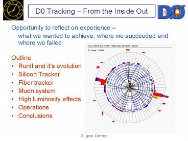
D0 Tracking From the Inside Out
- Opportunity to reflect on experience
- what we wanted to achieve, where we succeeded
and where we failed - Outline
- RunII and its evolution
- Silicon Tracker
- Fiber tracker
- Muon system
- High luminosity effects
- Operations
- Conclusions
2
Landscape circa 1990
- Lets go back to 1990 D0 wasconsidering an
upgrade as theoriginal (RunI) detector was being
installed to accommodate an upgraded
Tevatron/Main Injector - Reduced crossing interval 3.2ms ? 396(132) ns
- Magnet a break from the UA1 inspired no magnet
philosophy - Improved tracking
- Improved muon detector
- Silicon vertex detector
- Develop a tracking culture
- The Physics Landscape
- LHC/SSC will be on by 1997 and dominate high pt
physics - Top quark not yet discovered
- CDF shows B physics capability of collider
detectors and utility of vertex detectors - B factories ?
- Mixed high pT and B physics emphasis in design
3
Run One D0 Experience
- Small angle muon chambers were very busy can
they be adequately shielded and keep good high h
acceptance? - D0 tracker performed very poorly in rz chambers
used charge division and delay lines for z
information. - CDF had much better J/y ? mm yields than D0, due
to thinner iron, lower pT. - Can good high h tracking be preserved in spite of
the long luminous region?
- Detailed MARS and Geant muon shielding
simulations. - neutrons were a problem
- complex shield design
- timing important
- Use small angle stereo in central tracker, small
and large angle in silicon, short barrels - Add an inner scintillation counter layer to
reduce muon pT threshold - Disk/barrel design of the silicon tracker to
preserve high h resolution
4
The Shifting Playing field
10 int/xing
- Integrated luminosity
- 2 fb-1 ?15 fb-1(IIb)
- ?between 4 and 8 fb-1
- Crossing interval was planned to decrease from
396 ns to 132 ns in RunIIb. It will now stay at
396 ns - There was hope that the luminous region would
decrease from 30 to 15 cm. - Actual instantaneous luminosity can be 2x
average due to bunch-to-bunch variations - Luminosity leveling?
8x10312x1032 5x1032
5
Tracker Design
- Tracker hardware design was based on large
acceptance in h. - Used mixed disk/barrel system to maintain good
resolution and efficiency with long (25cm)
luminous region - Large area H disks precise point at high Z to
maintain momentum resolution - Route cables between barrel ladders no lost
spaceat the barrel/disk interface - Resulted in a complex silicon mechanical design
and a challenge to the Monte Carlo
6
D0SMT Disk/Barrel Design
Support andcables
disk
barrel
7
The D0 Run2 Detector
Muon System
Fiber Tracker
D0SMT
8
Tracker Technology Decisions
- Original silicon detector design was for 2 fb-1.
RunIIb physics studies (Higgs) indicated that
experiments (and accelerator) should attempt 15
fb-1 (2002) - Silicon technology was based on SSC RD
(double-sided) subsequent LHC RD showed this was
not the best choice - Rad hard chip technology being phased out at many
vendors - We had the last run at UTMC for SVX2 (1996)
- Chip design tools poor
- Replaced by deep submicron 2002
- D0 decided to use SVX2 rather than SVX3
- Bird in the hand (working chip little did we
know) - Did not need multiple buffering at L1 (now limit
to trigger) - Too much work to develop simultaneous low noise
readout/daq (probably true-big effort at CDF) - VLPC/SciFi development for tracking all new
technology high risk but excellent for fast
triggering
9
Tracker Parameters
- s(pT)/pT2 0.0152 (0.0014pT)2
- s(PV) 35 mm
- s(IP) 15 mm, pT gt10 GeV
Maximum 12 hits at h0ignoring overlaps
10
SMT Operations
F wedge noise
- SVX2 chip is not very robust
- Needs to be read out every 30 seconds or current
goes up causing trips heartbeat trigger
installed - Very sensitive to supply voltage, signal quality
- Channels come and go 15 disabled at any one
time - Wedge detectors from Micron show serious grassy
noise beginning several months after the start
of RunII
bias current
11
Microdischarge
- Many double sided detectors have low p-side
microdischarge junction breakdown voltage - Limits voltage applied to a side not total bias
- The sensitive side switches from p to n after
type inversion - The total voltage allowedincreases after type
because the oxide chargelowers the n-side
fields - Not yet a practical limit tooperations
12
Booster Radiation Studies
- Spare detectors were exposed to 8 GeV booster
proton irradiation - Full readout/laser test measurements at each
point - Most behaved normally
- Double metal 90 degree detectors (DSDM) showed
anomalous Vbias slope limit to SMT lifetime?
1 fb-1
13
SMT Radiation Studies
- We now have enough experience to measure long
term behavior - Use charge collection and n-side noise
- Charge collection data taken at regular intervals
- DSDM detectors now look normal probably charge
annealing in PECVD dielectric - Expect the SMT to survive to 5-7 fb-1
14
SMT Radiation Studies
- Measure flux using leakage current evolution
- Measure depletion voltage with charge collection
and noise
Noise vs voltage
15
Run II Results
16
Beam Protection
2003 beam loss incident
- Beam losses are not uncommon
- 2003 CDF Roman Pot into beam
- Kicker prefires, Quenches, Shot setup
- LHC/TeV 1000 in beam power
- D0 has two radiation monitoring/abort systems
- BLM - argon gas ion chambers circa 1980
- Originally developed for AD/CDF
- Provides Tevatron abort_at_12 rad/s
- 10 m from IP
- NIKHEF finger diodes
- 24 one cm photodiodes 2.6 cm to 9.5 cm from beam
- 106 dynamic range scaler/ADC
- Not used for abort due to SMT readout noise
Holes in 2 upstream components
17
Beam Monitoring
- Large dynamic range and low radius of the fingers
allow detailed studies of beam effects and
incidents - Understand losses at various stages of the cycle
for some losses have dominated by luminosity
Scaler count rate vs time as solenoidramps down
looper plateau 0.8 T
Finger scalers
Finger ADCs
Shot Setup
18
Fiber Tracker CFT/CPS
- CFT - 8 doublet layers of 0.835 mm fibers
(xu,xv..) use high QE VLPC technology - Few layers-require high e
- High occupancy for inner layers
- Fewer hits than gas-based chamber, but more
radiation hard, amenable to fast (L1) track
trigger with FPGAs - CPS layer of triangular scintillator outside of
solenoid
Fiber tracker Clear waveguides
19
CFT Operations
- AFE readout of VLPC system for CFT and
preshower - SVX2 dynamic range 200 MIPS front end integrator
is subject to saturation at high L - Discriminator crosstalk to ADC
- Crossing-to-crossing pedestal variations
- Replacing AFE with AFEII
- No SVX2
- New trip-t chip clean discriminator output and
timing
crossing
20
Tracking Performance
Low momentumtracking option
de/dx particle ID
21
Muon System
- Muons are at the heart of much D0 physics
- Run II optimization
- Chambers at high h were too noisy
- Most noise hits are out of time with collision
muons - Detailed study/model of shielding
- Lower pt threshold for B physics to 1.5 GeV
- Detailed shielding redesign
- 50 cm of steel hadrons and e/g
- 12 cm of polyethylene - neutrons
- 5 cm of lead - gamma rays
- Reduction in particle fluxes by a factor of
50-100 (GEANT/MARS) - Run 1 muon detector occupancies have been in the
5-10 level - Run 2 muon detector occupancies are in the
0.05-0.1 level
22
Run I
Small angle muon chambers
Typical Run I event
Run II
23
Muon Chambers and Counters
24
Muon System
- Added fast counters to reject halo
- Added counter layer before m filter with 1.5
GeV Pt threshold - Level 1 muon-track match trigger
- Result x150 J/y yield over Run I
competitive B physics
Run 1
Muon h in J/psi events
25
Monte Carlo
- Difficult to properly model complex SMT cable
paths - Use ee- conversions to map material and
validateMC - Initial version was missing top of support
cylinder - Inclusion of ladder and support details is an
ongoing effort - Tracking system resolutions and errors still not
fully understood.
Data
Monte Carlo
26
Understanding Uncertainties
- Are the assigned uncertainties correct?
- Hit position algorithm based on cluster size
- Study IP resolution of PV tracks based on hit
patterns - Scale to fit beam convoluted IP distribution
- Hampered by the loss of raw hit data early in the
data stream
27
Tracking CPU
- Tracking CPU time has always been a problem in
this design minimal layer in outer tracker - Currently our L3 rate is limited to 50 hz - the
rate at which data can be reconstructed will be
raised - Serious problem at high luminosity
Black total tracking Red pattern rec Green
HTF patt rec Blue AA patt rec Pink track
fit HTF, not AA, is the current culprit
Improvement by better treatment of large (looper)
clusters
28
High Luminosity Tracking
With our current hardware and algorithms both
efficiency and purity will degrade at high
luminosity
29
Study of Luminosity Effects in Data
J/y ? mm as a function of the number of tracks in
the event
30
Coping with High Luminosity
- AFE II project (CFT readout)
- Fix saturation, pedestals, add timing to CFT
- Layer 0 (M. Weber)
- Tracking algorithms tradeoffs between
thresholds and speed - Luminosity leveling vary b during the store to
provide uniform luminosity with similar integral - Trigger upgrades
31
Operations
- Experiment is collecting data efficiently 5
dead time - Solenoid magnet developed a heat leak limited
to 96 of full field - Limit thermal and ramp cycles
- Operational channels
- SMT 87
- CFT 99 (was 99.9)
- Muon 99.8
- CAL 99.9
32
What we did ..
- Right
- Carefully tested most detector types extensive
system tests - Excellent mechanical quality and stability
- Tracking system provides excellent h and momentum
acceptance, tracking to 180 MeV - Muon system design shielding and timing
- It all works to produce physics
- Wrong
- Upgrade was ambitious all detectors should be
properly supported in hardware and software - Hardware and software groups did not always
interact effectively. - Cost and schedule was too much of an early
concern - Changing plans from FNAL and accelerator
33
Conclusions
Bs mixing
WZ ? trileptons
W mass
B semileptonic
Recommended
