
Kelvin Probe Measurements: PowerPoint PPT Presentation
1 / 1
Title: Kelvin Probe Measurements:
1
Kelvin Probe Measurements Investigations of
the Patch Effect with Applications to ST7 and
LISA N. A. Robertson1, J. R. Blackwood2, S.
Buchman1, R. L. Byer1, J. Camp2, D. Gill1, J.
Hanson1, S. Williams1, P. Zhou1 1Stanford
University, 2Goddard Space Flight Center
- LISA Laser Interferometer Space Antenna
- Joint ESA/NASA mission to detect gravitational
waves - Detection using laser interferometry between
- freely-floating test masses
- Test masses located in 3 spacecraft 5 million
km apart - ST7
- NASA demonstrator mission to fly on ESAs LISA
Pathfinder - Test of technologies for LISA
- Key technology design of gravitational
reference sensor - Gravitational Reference Sensor
- Gold/platinum cubic test mass with gold coating
- Test mass flown drag free using capacitive
position sensing - and feedback to thrusters on spacecraft
- Residual acceleration noise requirement 3 x
10-14 m/rt Hz
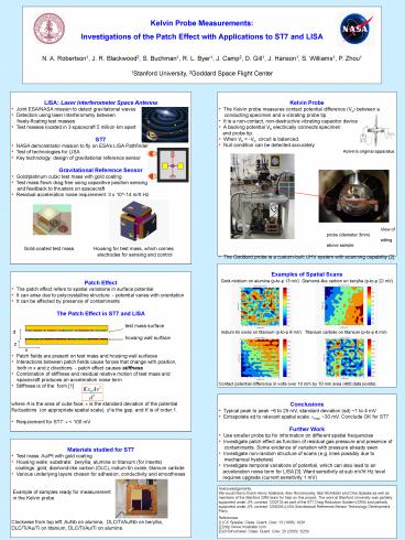
- Kelvin Probe
- The Kelvin probe measures contact potential
difference (Vc) between a - conducting specimen and a vibrating probe tip
- It is a non-contact, non-destructive vibrating
capacitor device - A backing potential Vb electrically connects
specimen - and probe tip.
- When Vb -Vc, circuit is balanced.
- Null condition can be detected accurately
- Kelvins original apparatus
- Examples of Spatial Scans
- Gold-niobium on alumina (p-to-p 13 mV)
Diamond-like carbon on beryllia (p-to-p 22 mV)
- Indium tin oxide on titanium (p-to-p 6 mV)
Titanium carbide on titanium (p-to-p 6 mV)
- Patch Effect
- The patch effect refers to spatial variations
in surface potential - It can arise due to polycrystalline structure
- potential varies with orientation - It can be affected by presence of contaminants
- The Patch Effect in ST7 and LISA
- test mass surface
- d
- housing wall surface
- z
- x
- Patch fields are present on test mass and
housing wall surfaces - Interactions between patch fields cause forces
that change with position, - both in x and z directions - patch effect
causes stiffness - Combination of stiffness and residual relative
motion of test mass and - spacecraft produces an acceleration noise
term - Stiffness is of the form 1
- Conclusions
- Typical peak to peak 6 to 25 mV, standard
deviation (sd) 1 to 4 mV - Extrapolate sd to relevant spatial scale vmax
30 mV. Conclude OK for ST7 - Further Work
- Use smaller probe tip for information on
different spatial frequencies - Investigate patch effect as function of
residual gas pressure and presence of - contaminants. Some evidence of variation with
pressure already seen - Investigate non-random structure of scans (e.g.
lines possibly due to - mechanical hysterisis)
- Investigate temporal variations of potential,
which can also lead to an - acceleration noise term for LISA 3. Want
sensitivity at sub mV/rt Hz level - requires upgrade (current sensitivity 1 mV)
- Materials studied for ST7
- Test mass Au/Pt with gold coating
- Housing walls substrate beryllia, alumina or
titanium (for inserts) - coatings gold, diamond-like carbon (DLC),
indium tin oxide, titanium carbide - Various underlying layers chosen for adhesion,
conductivity and smoothness - Example of samples ready for measurement
- in the Kelvin probe
- Clockwise from top left AuNb on alumina,
DLC/Ti/Au/Nb on beryllia, - DLC/Ti/Au/Ti on titanium, DLC/Ti/Au/Ti on alumina
Acknowledgements. We would like to thank Henry
Abakians, Alex Romanovsky, Bob McAllister and
Clive Speake as well as members of the Stanford
GRS team for help on this project. The work at
Stanford University was partially supported under
JPL contract 1232133 as part of the ST7 Drag
Reduction System (DRS) and partially supported
under JPL contract 1258294 (LISA Gravitational
Reference Sensor Technology Development
Plan). References 1 CC Speake, Class. Quant.
Grav. 13 (1996) A291 2 http//www.mcallister.co
m 3 B Schumaker, Class. Quant. Grav. 20 (2003)
S239
Recommended
