
Layer 0 Preparations PowerPoint PPT Presentation
1 / 15
Title: Layer 0 Preparations
1
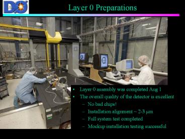
Layer 0 Preparations
- Layer 0 assembly was completed Aug 1
- The overall quality of the detector is excellent
- No bad chips!
- Installation alignment 2-3 mm
- Full system test completed
- Mockup installation testing successful
2
History
- The RunIIb silicon upgrade was designed to
replace the radiation damaged D0SMT cancelled
by the Director 2 years ago - Sept 2003. - Soon after we proposed a radiation hard inner
layer detector to - Extend the lifetime of the SMT
- Smaller radius, low mass - improve impact
parameter resolution b tagging, lifetime
resolution. - Provides an additional hit for pattern
recognition. - Uses RD and people who developed the RunIIb
technology
3
L0 Design
- Must fit in the 23 mm radius opening in SMT
supports - Low mass, precise hit as close as possible to the
IP (ref. CDF L00) - CDF L00 had serious coherent noise problems
major effort invested in grounding, shielding,
and system testing - Use RunIIb components and RD
- Hybrid, SVX4, analog cables, beam pipe, sensors,
readout components very similar or identical to
RunIIb designs. - New carbon fiber support structure using IIb
concepts and experience - New pitch adapter to accommodate dual sensor
pitch with single cable type - New installation scheme-required understanding of
SMT support locations and openings - Grounding and isolation constant concerns L0 is
a great antenna
4
Sensor Design
- Pitch values selected to provide gt98 coverage
- Sensor length shorter near IP, lower occupancy,
equalize noise - Low radius, wide sensors imply wide clusters
near the edge, position dependent errors - Intermediate strips to improve resolution (want
good signal/noise) - Single sided HPK sensors with 300V bias
radiation hard to 15 fb-1 (tested to 500V)
intermediate strip
50-100mmstrip pitch
Liverpool L00 studies
5
L0 Components
- Layer 0 consists of
- 48 sensor/analog cable/readout modules of 8 types
- 7 and 12 cm sensors
- x 4 analog cable lengths
- 71, 81 mm pitch
- SVX4 readout chips, BeO hybrids
- Digital jumper cables
- Carbon Fiber Support structure
- Readout Components
- Junction cards/twisted pair cables/adapter cards
- Installation components
- Supports attached to the Run2a SMT structure
- Tooling to install and align Layer 0 and extract
the Run2a beampipe
Analog cable
SVX4
Hybrid end
bumpers
analog cable
pitchadapter
meshspacer
wrap-around
Installed module sensor end
6
Noise and Grounding
- The long (34 cm) analog cables and
sensitive SVX4 make L0 especially susceptible to
coherent noise. CDF L00, a similar design, has
serious coherent noise problems. These were
addressed in L0 by providing an excellent ground
reference and minimizing floating capacitance - Copper-kapton mesh ground plane co-cured on the
CF support structure - Low inductance strip connections to sensors and
hybrids - Minimum spacing (gt400 ?m) between cables and
conducting structures to limit capacitive coupling
7
Noise and Grounding II
L0 can potentially cause a ground loop between D0
north and south. Differentially isolated adapter
cards are used to break the loop. This increases
sensitivity to external pickup. This is solved
by ferrite isolation of all power lines. RTDs
passing under analog cables also will require
filters.
- Noise performance
- Total noise is 2-2.5 ADC counts(1 MIP 30 ADC
counts ? S/N gt12-15) - Readout and noise were tested to be stable also
during temperature and HV scans.
Diff. Noise x10
PED RMS x10
PED
Performance with real time pedestal subtraction
8
Component QC and Testing
- Component and assembly testing
- Sensor probe tests (VI curves, probe testing on a
sample) - Pitch adapter visual inspection (require 100
good strips) - Analog cable plating designed to make it easy to
spot open channels - Burn-in
- Hybrid before and after encapsulation
- Module after assembly and after final bond
encapsulation - Module VI curves, quick readout tests after
assembly - Long term tests of selected modules
- Inspection and testing of DJC, twisted pair at KU
and Fermilab - Extensive CMM measurements of L0 support
structures - lt0.1 bad channels in assembled detector
9
System and Mockup Tests
- Electrical structure
- Used first prototype support structure (good
electrically) - Used 10 pre-production modules
- Tested grounding schemes, cable spacing, isolated
grounding scheme - Full system test
- Two phases, half and full system
- Used final versions of electronics and cables
components to be installed in D0 - Used for testing grounding, isolation, cooling
and power delivery - Cold test to -8 deg C
- Mockup tests at Lab 3 and DAB
- Confirm installation techniques and tooling
- Practice and develop procedures
- Make sure that the parts fit
10
L0/SMT Readout
HV
LV
WeinerSupplies
Fuse Panel
Bulk LV Power Supplies
I B
Interface Board Crates (8x18)
Cathedral
Around Iteraction Region
CLKs
Twisted pair
Jumpercard
19-30 High Mass Cable (3M/80 conductor)
2 Chiphybrid
Adaptor card
Digital Jumper cable
CLKs
Analog cable
25 High Mass Cable (3M/50 conductor)
Cathedral
Horse Shoe
I,V,T Monitoring
Sensor
New for L0
Optical Link 1Gb/s
17 twisted pair cables
SEQ
SEQ Controller
Sequencer Crates (6x20)
HV breakout box
Serial Command Link
VRBC
VRB
S B C
Platform
SBC
25 twisted pair cables
VRB Crates (12x10)
HV fanout 1gt4
VME Crates (4x3)
HV Crates (8x62x4)
MCH2
Monitoring SDAQ
PDAQ (L3)
MCH3
MCH2
PowerPCs and Single Board Computers are accessed
thru Ethernet
11
Dzero Tests
- Four L0 modules/hybrids were installed in D0
during the fall 2004 shutdown - Used to debug SVX4 readout with full D0 readout
system - Develop download and diagnostic GUIs
- Exercise SVX4 power supplies, controls, adapter
cards - Accommodate SVX4 data through online and offline
software - We see 5 count pedestal offset for crossing 119
related to reset and control signals - SVX4 readout test crate (x79)
- Controlled testing of SVX4 readout
- Development of firmware
modules
hybrids
12
Technical Readiness Review
- Run2b project installation technical readiness
review was held Sept 27 - This committee finds the Layer 0 detector to be
of excellent quality, both electrically and
mechanicallyFrom the mechanical point of view,
the D0 Layer 0 is ready to installThe software
required for detector control and monitoring, as
well as data unpacking, appears to be essentially
in place - Recommendations
- We recommend additional studies be performed in
order to complement the existing information from
burn-in tests. Readout tests performed at D0 are
encouraging, although some issues with pedestal
stability vs bunch crossing number have been
uncovered, which should vigorously investigated
and resolvedcontinued effort to study and
improve the grounding/shielding of the Layer 0
detector. Given that the detector might not be
installed for many months, additional work could
be done to minimize the risk of an unsuccessful
installation We recommend planning for a
software challenge to shake down all components - http//www-clued0.fnal.gov/juste/L0_TRR_Report.pd
f - http//www-clued0.fnal.gov/juste/L0_TRR_Report.do
c
13
Timeline
- RunIIb silicon cancellation September 3, 2003
- L0 TDR to FNAL October 28, 2003
- Mechanical design specified December 15, 2004
- Sensors received July 31 2004
- Analog cables received August 10, 2004
- First test modules produced September 2004
- First production modules January 2005
- First module installed June 2, 2005
- Last module installed August 1, 2005
- System tests July 1-12, Aug 14 Sept 14
14
Remaining Work
- Mockups
- Practice gluing of L0 and adapter card supports
to SMT2a support structure, another installation
run-through - SiDet
- Cosmic tests using spare modules
- Final mechanical measurements
- Testing of power supply and filter boards
- Readout at DAB
- Pedestal jump at crossing 119
- Write final procedures and ORCs
- D0 notes on modules, system tests, electronics,
mechanics, NIM paper
15
Conclusions
- The detector looks very good
- No bad chips
- Tiny leakage currents
- SVX 4 is robust and reliable
- Noise is low
- No pinholes, few bad channels
- Preparing for installation
Recommended
