
Overview PowerPoint PPT Presentation
1 / 1
Title: Overview
1
H. Hur T. Nagata T. Kaga M. Tomizuka
Automatic Transmission Modeling and Control
Applications
Overview An automatic transmission model is
developed using Finite State Machine (FSM)
modeling techniques. The choice of FSM as a
modeling framework reflects the hybrid nature of
automatic transmission in which each discrete
gear position involves a unique continuous time
dynamics. Controller design concept based upon
the presented FSM automatic transmission model is
proposed together with its application to Shift
Quality Control and interfacing with other
powertrain elements such as engine and wheel.
Control Applications Interfacing with Engine
and Powertrain Smoothing of automatic
transmission output torque during gear shift can
be combined with engine torque control to add
more flexibility. In such cases, the ECU will
receive information on the current AT state from
the TCU so that engine control can be adapted to
different shifting phases. Other applications
involving, but not restricted to AT modeling,
include (1) reduction of shock related to
backlashes in powertrain gears at torque
change, (2) dealing with changing wheel-road
surface interactions.
Plant-Controller Configuration The FSM Automatic
Transmission (AT) model is to be connected with
Transmission Control Unit (TCU) where a dedicated
controller exists for each state or a set of
states in the AT. Sensor data from AT is input
into the TCU, by which the TCU determines which
current state the AT model takes. A corresponding
controller will be assigned based upon the
determined state and its outputs become the
actuation commands to the AT model. TCU also
takes inputs from the Engine Control Unit (ECU)
for engine variables and from the driver for gear
selection.
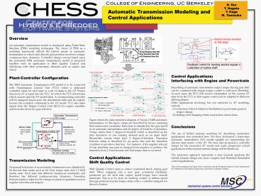
Figure shows the state-transition diagram of
Toyota U140E automatic transmission. In this
figure, states are described by boxes containing
their names and constraints. Each state is
classified by the gear speed of an automatic
transmission and its degree of freedom of
dynamics. Torque states have 1 degree-of-freedom
which is described as the time derivative of one
rotating element such as an input shaft.
Meanwhile, inertia states have 2
degree-of-freedom. Transition between states is
described by an arrow line and the transition
condition is put above that line. For instance,
if the angular velocity of rear planetary sun
gear is changed from negative to positive, the
transition from 1-2 inertia state into 2nd torque
state is occurred.
Conclusions The use of hybrid systems modeling
for describing automotive applications was
presented here. We have developed a finite-state
automatic transmission (AT) model suitable for
representing the discrete state nature of the AT.
We have also proposed a controller design for the
presented AT model and some prospected control
applications where hybrid systems design will be
beneficial. The proposed approach represents a
step towards applying the hybrid systems design
into more complex and flexibility-demanded
control applications. This work was supported by
Toyota Motor Corporation and the Mechanical
Systems Control Laboratory in the Department of
Mechanical Engineering, University of California,
Berkeley.
Control Applications Shift Quality
Control Shift Quality Control aims to reduce
undesired shock during gear shift. When engaging
into a new gear, actuations (hydraulic pressures)
are set such that output speed/torque have smooth
transients. This is to be done by tracking
control of turbine speed through pertinent
inertia/torque states with a controller assigned
for this set of states.
Transmission Modeling Dynamical behaviors of an
automatic transmission are classified by its
discrete-time states such as 1st Gear torque
state and 1-2 shift inertia state. Each state has
different dynamical constraints and therefore has
different continuous-time dynamics. Transition
between states is taken by the change of physical
quantities such as angular velocities and
torques.
Recommended
