
Chapters 8 PowerPoint PPT Presentation
Title: Chapters 8
1
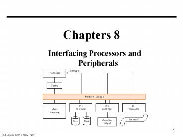
Chapters 8
- Interfacing Processors and Peripherals
2
Interfacing Processors and Peripherals
- Focus of processor design Performance
- I/O Design affected by many factors
(expandability, resilience) - Performance in an I/O system may be primarily
about access latency throughput
connection between devices and the system - A variety of different users (e.g., banks,
supercomputers, engineers)
3
Impact of I/O on System Performance
- Example
- Suppose we have a benchmark that executes in 100
seconds of elapsed time, where 90 seconds is CPU
time and the rest is I/O time. If CPU time
improves by 50 per year for the next 5 years but
I/O time does not improve, how much faster will
our program run at the end of five years? - I/O may become a bottleneck, especially with fast
CPUs - I/O performance may be
- How much data can we move through the system in a
certain time? - How many I/O operations can we do per unit of
time?
4
I/O Devices
- Very diverse devices behavior (i.e., input vs.
output) partner (who is at the other end?)
data rate
5
Accessing I/O Devices
- Every device controller has a number of
registers to reflect the status of the device and
to accept commands - The CPU can access the device registers
- Memory mapped I/O versus isolated I/O
- There are two methods for the CPU to know the
status of an I/O device - Polling periodically read the status registers
- Interrupt device interrupts the CPU when a
change occurs
6
I/O Example the mouse
- Registers to store X and Y positions (counters)
- Registers to indicate the status of buttons
- Cursor is updated by the CPU to reflect the
contents of counters
20 in Y -20 in X
20 in Y 20 in X
20 in Y
20 in X
Initial Position
-20 in X
-20 in Y -20 in X
-20 in Y 20 in X
-20 in Y
7
I/O Example Disk Drives
- Typically
- 1000 - 5000 tracks per surface
- 64 - 200 sectors per track
- 512 Bytes per sector
- All tracks have the same number of sectors
- real/write heads
- Cylinders
- To access data
- wait time until disk is not used for other
transactions - seek position head over the proper track
- rotational latency wait for desired sector
- transfer grab the data (one or more sectors)
- controller time
8
I/O Example Disk Drives
- Typical specification
- 3600 - 7200 RPM ( approximately 16 - 8 ms per
revolution) - Sector address plate , track , sector
- A file is physically stored as an ordered list of
sectors - Average seek time over all possible seeks (8 - 20
ms) - Rotation latency 0.5 time for a full rotation
(1/RPM) 4.2 to 8.3 ms - Transfer rate 2 to 15 MB/sec -- may improve by
adding caches on disk - Example 512 bytes / sector, 5400 RPM, average
seek time 12 ms, Controller delay 2 ms,
transfer rate 5 MB/sec. What is average disk
access time? Assume disk is idle so that there is
no waiting time.
9
I/O Example Networks
- Major medium used to communicate between
computers - Point to point networks
- Example RS232 0.3 - 19.2 Kb/sec over short
distances - Local area networks (LAN)
- Example Ethernet a bus with multiple masters
- 10 - 100 Mb/sec over hundreds of meters
- Long-haul networks usually switch networks
- packet switch
- usually uses a stack of protocols
- example TCP/IP (Transmission Control Protocol
/Internet Protocol) - 100 Mb/sec - 1Gb/sec
- Another example ATM (Asynchronous Transfer
Method) - 155 Mb/sec - 2.5 Gb/sec
10
Buses
CPU
I/O Device
I/O Device
I/O Device
M
a
i
n
m
e
m
o
r
y
- shared communication link ( one or more wires)
- address lines
- data lines
- control lines
11
Advantages and disadvantages of Buses
- Advantages
- Versatility
- New devices can be added easily
- Peripherals can be moved between computers that
use the same bus standard - Low cost a single set of wires is shared in
multiple ways - Mange complexity by partitioning the design
- Disadvantage
- Creates communication bottleneck
- The maximum bus speed is largely limited by
- Length of the bus
- The number of devices on the bus
- the need to support a range of devices with
varying latencies and transfer rates
12
Master Versus Slave
- A bus transaction includes two parts
- Issuing the command ( and address) - request
- Transferring the data - action
- Master is the one who starts the bus transaction
by - Issuing the command (and address)
- Slave is the one who responds by
- Sending data to the master if master asks for
data - Receiving data from the master if the master
wants to send data - A bus may only have one master device -- all
other devices are slaves - A bus may have more than one possible master
- Need some arbitration to determine the master at
any given time
13
Types of Buses
- Processor-Memory Bus ( design specific)
- short and high speed
- Only need to match the memory system
- Connects directly to the processor
- I/O Bus (industry standard)
- Usually lengthy and slower
- Need to match a wide range of I/O devices
- Connects to the processor-memory bus or the
backplane bus - Backplane Bus (standard or proprietary)
- An interconnection structure within the chassis
- Allows processor, memory, and I/O devices to
coexist - Cost advantage one bus for all components
14
A Computer with One Bus
Backplane Bus
- A single (backplane) bus is used for
- Processor to memory communication
- Communication between I/O devices and memory
- Advantage Simple and low cost
- Disadvantage slow -- the bus can become a major
bottleneck - Example IBM PC - AT
15
A Computer with two Bus System
- I/O buses tap into the processor - memory bus via
bus adaptors - Processor - memory bus mainly for processor -
memory traffic - I/O buses provide expansion slots for I/O
devices - Example Apple Macintosh II
- NuBus Processor, memory, and a few selected I/O
devices - SCCI Bus the rest of the I/O devices
16
A Computer with Three Bus System
- A small number of backplane buses tap into the
processor memory bus - Advantage Processor-memory bus can be made much
faster than the backplane bus. - I/O system can be expanded by plugging many I/O
controllers and buses into the backplane without
affecting the speed of processor-memory bus - Example IBM RS/6000 and Silicon Graphics
Multiprocessors
17
Synchronous vs. Asynchronous
- Synchronous Bus
- use a clock in the control lines
- A fixed protocol for communication that is
relative to the clock - T1 Transmit address and read command
- T2 Memory responds
- Advantage involves very little logic and can run
very fast - Disadvantage every device must operate at same
rate and clock skew requires the bus to
be short - Asynchronous Bus
- It is not clocked
- It can accommodate a wide rage of devices
- It can be lengthened without worrying about clock
shew - It requires a handshaking protocol
18
Asynchronous Protocol for Read (example)
ReadReq
1
3
Address
2
2
4
6
Ack
5
7
DataRdy
6
4
Data
Ack
Address
ReadReq
Master
Slave
Data
DataRdy
19
Asynchronous Protocol for Write (example)
WriteReq
1
3
Address
2
2
4
Ack
6
5
7
DataRdy
Data
Ack
Address
WriteReq
Master
Slave
Data
DataRdy
20
Arbitration Obtaining Access to the Bus
- One of the most important issues in bus design
- How is the bus reserved by a device that wishes
to use it? - Chaos is avoided by a master-slave arrangement
- Only the bus master can control access to the
bus - it initiates and control all bus requests
- A slave responds to read and write requests
- The simplest system
- Processor is the only bus master
- All bus requests must be controlled by the
processor - Major drawback the processor is involved in
every transaction
21
Multiple Potential Masters Need for Arbitration
- Bus arbitration scheme
- A bus master wanting to use the bus asserts the
bus request - A bus master cannot use the bus until its request
is granted - A bus master must signal to the arbiter after it
finishes using the bus - Try to balance two factors
- Bus priority the highest priority device should
be serviced first - Fairness even the lowest priority device should
eventually get served - Bus arbitration can be divided into four broad
classes - Daisy chain arbitration single device with all
request lines - centralized, Parallel arbitration (requires an
arbiter), e.g., PCI - Distributed arbitration by self selection, e.g.,
NuBus used in Macintosh - Distributed arbitration by collision detection,
e.g., Ethernet
22
Multiple Potential Masters Need for Arbitration
- Bus Overview
- What is it? - shared communication line
between subsystems. (PH Figure 8.1) - Design factors
- Speed is limited by length and number
of devices. - Must support a range of latencies and
data rates. - Structure
- Data lines - carry information
- Address lines - carry address
(sometimes multiplexed on data lines) - Control lines - signal request and
acknowledgement - Types (PH Figure 8.9)
- Processor-memory - short, high-speed
- I/O buses - long, many devices,
usually don't connect directly to memory - Backplane - balance I/O - memory with
CPU-memory communication - Asynchronous bus
- Not clocked
- Uses handshaking protocol (look at PH
Figures 8.10 and 8.11) with control lines (e.g. - ReadReq, DataReq and Acq)
Recommended
