
Design of Tension Members PowerPoint PPT Presentation
1 / 13
Title: Design of Tension Members
1
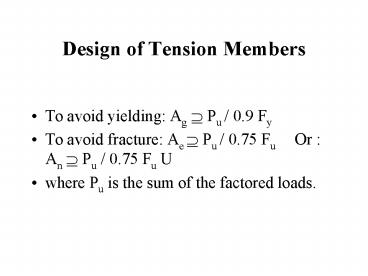
Design of Tension Members
- To avoid yielding Ag ? Pu / 0.9 Fy
- To avoid fracture Ae ? Pu / 0.75 Fu Or
An ? Pu / 0.75 Fu U - where Pu is the sum of the factored loads.
2
Design of Tension Members
- If the axial load in a slender tension member is
removed and small transverse loads are applied,
undesirable vibrations or deflections may occur.
Thus AISC recommends - r ? L/300 ( not for cables or rods)
- where r is the minimum radius of gyration of the
cross section and L is the length of the member.
3
Threaded Rods and Cables
- When slenderness is not a consideration, circular
rods and cables are often used (hangers,
suspended bridges). - Rods are solid and cables are made from
individual strands wound together. - Threading the end of a rod reduces the cross
sectional area (upset end prevents such
reduction, but is expensive).
4
(No Transcript)
5
Threaded Rods and Cables
- ?t Pn 0.75 (0.75 Ab Fu)
- Ab nominal (unthreaded) area
- It is common to use a min diameter of 5/8 in. for
rods.
6
Threaded Rods and Cables
- A strand consists of individual wires wound
helically around a centrl core. - A wire rope is made of several strands laid
helically around a core.
7
Tension Members in Roof Truss
- Trusses are used where the cost and weight of a
beam could be prohibitive (long spans). - A truss may be thought of as a deep beam with
much of the web removed. - Tension members in roof trusses include some
truss members and sag rods.
8
Sag Rods
- Sag rods are used to provide lateral support for
the purlins (to prevent sag in direction parallel
to a sloping roof due to vertical applied loads). - They are designed to support the component of
roof loads parallel to the roof.
9
(No Transcript)
10
(No Transcript)
11
Sag Rods
- Each segment between purlins is assumed to
support everything below it thus the top rod is
designed for the load on the roof area tributary
to the rod, from the heel of the truss to the
peak.
12
(No Transcript)
13
Sag Rods
- The tie rod between ridge purlins must resist the
load from all of the sag rods on either side.
Recommended
