
Mechanical Structure of ICAL Detector for INO PowerPoint PPT Presentation
1 / 47
Title: Mechanical Structure of ICAL Detector for INO
1
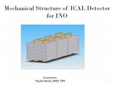
Mechanical Structure of ICAL Detector for INO
Presented by Piyush Verma, DHEP, TIFR
2
What is INO?
The India-based Neutrino Observatory (INO) is a
proposed pure-Science underground
laboratory. The detector housed in the INO
underground laboratory will be a magnetized Iron
Calorimeter detector (ICAL). Its primary goal
is to study the properties and interactions of
weakly interacting, naturally occurring
particles, called neutrinos.
3
Location
Between Ooty and Mysore in the Nilgiri Hills.
Lab will be an underground Cavern with a rock
cover of atleast 1 KM on all sides.
4
Detector Cavern
5
Detector Cavern
6
Detector Cavern (Details)
7
(No Transcript)
8
What will be the detector that will be housed at
INO?
The detector housed in the INO underground
laboratory will be a magnetised iron calorimeter
detector (ICAL). It is a static device without
moving parts. Charged particles produced in
neutrino interactions can be detected by means of
an iron calorimeter (ICAL) detector. Iron layers
will be sandwiched with the active detector
material that will detect whenever a charged
particle passes through it. The detector will be
of dimension 16 M x 48 M x 14.4 m ht. This will
be divided into 3 sub modules of size 16m x 16m x
14.4m ht. Each sub-module will contain approx.
17KT of soft Iron.
9
The Iron plates will be stacked with a gap of
40mm between consecutive layers. Each layer will
have 32 Iron plates of dimension 2m x 4m x 56mm
thick put in one plane to make a 16m x 16m layer.
10
Design Requirements of the Detector Stack Assembly
- Total width and length of detector structure will
be 16m x 48m, constructed in three - modules of 16m x 16m each.
- Total weight of steel plates forming the
detector structure is required to be 50kT. - Proposed site falls under Seismic zone II. The
structure should withstand the - seismic acceleration of 0.073 m/sec2 as per
the seismic zone requirement. - The flatness of each detector plates should be
less than 2mm over its entire surface. - The stack should be formed without welding
process. It should also have minimum - machining for minimizing the cost.
- Each layer should be magnetically isolated from
neighbouring layers. - The gap between the adjacent plates in the same
layer should be minimum to - reduce the magnetic loss due to air gaps.
- The detector stack should have provision for
putting magnetic coils based on the - magnet design.
11
Design Philosophy of the Detector Stack Assembly
- To achieve the design constraints, the stack is
proposed to consist of 150 layers of soft iron of
the dimension 2m x 4m x 56mmthk. - Each layer will be separated from neighbouring
layer by 40mm spacing. There will be discrete
spacers between the layers of cross-section 40mm
x 80mm or 40mm x 40mm. - The spacers will be made of SS304.
- There will be 20 dia. press fitted pins (material
SS304) in the spacers, which will be used to
locate the plates during construction of detector
layers. - In one Road there are eight RPCs. Four to be
extracted on one side and the other four to be
extracted on the other side.
12
Cross Section of the Main Lab
13
ICAL Detector Stack with RPC Handling Trolley
14
ICAL Detector Stack Assembly
15
ICAL Detector Stack (Details)
16
ICAL Detector Stack (Plate Layers)
17
ICAL Detector Stack (Plate Types)
18
Plate Dimensional Details
Plate Type - I
Plate Type - II
Plate Type - III
19
ICAL Detector Stack (Spacer Types)
20
Spacer Dimensional Details
21
Schematic of Detector Assembly in the Stack
- With current design, the thickness of RPC with
all components assembled together is 30mm. - Three options for putting RPC in the stack
- Put RPC on Teflon rails for easy insertion and
extraction with 4mm gap on the top and 6mm gap on
the bottom side. Run gas lines and HV/LV lines on
the sides. - Same as above but with 6mm gap on top and 4mm gap
at the bottom. - Put RPC directly on the iron plates (no Teflon
rails) and run all the lines on the top of RPC.
Teflon Rails
Gas, HV,LV
Spacer Block
RPC
22
Schematic of Detector Assembly in the Stack
(contd.)
Spacer Blocks
HV,LV Gas
RPC
Iron Plate
23
RPC Handling Trolley
24
RPC Handling Trolley
25
Design of ICAL Foundation Structure
- Dead load on the ICAL Detector Foundation
Structure will be from the weight of the
following components - ICAL detector plates 4m x 2mx 56mm x 150 layers
- Spacer Plates of 40mm thick in between detector
plates at discrete locations. - RPC trays of size 1.84m x 1.84m x 30mm in the
gaps of detector plates. - Connecting pins of 20mm dia to connect spacer
plate Detector plates. - Magnetic coils having size 625mm x 80mm.
- Bearing Plate of 40mm thick on top of concrete
pedestals. - RPC handling trolley structure
- Fixtures like gas lines, electric wires, RPC
guiding Teflon rails, coil supports, magnetic
coil mounting bracket, etc. - No other live loads (which are the permanent
loads) are expected to act on to the detector
foundation structure throughout the service life
of the structure. - As ICAL detector is situated underground, no wind
loads are considered.
26
Seismic Analysis of ICAL Foundation Structure
- Design horizontal seismic coefficient for the
calculation of lateral earthquake forces acting
on to the foundation structure is given by - Ah(Z/2 ) x (Sa/g) x (I/R)
- Where
- Ah Design horizontal seismic coefficient
- Z Zone factor as per seismic map of India 0.10
(Seismic zone II) - Sa/g Average Acceleration Response Coefficient
(calculated based on rocky strata underneath of
soil bearing capacity of 92 t/m2 and having
damping of 5 as per clause no. 7.8.2.1 of
IS1893-part 4 for RCC Structures) - 2.5
- I Importance factor 1.75
- R Response Reduction Factor (represents ratio
of maximum seismic force on a structure during
specified ground motion if it were to remain
elastic to the design seismic force) - 3
- This gives Ah 0.073
27
Seismic Analysis of ICAL Foundation Structure
- Seismic calculation of ICAL detector foundation
structure summaries that 7.3 of total seismic
weight of ICAL detector structure is going to act
on to the structure as the lateral earthquake
forces and foundation structure has to be
designed to with stand the above force - Seismic forces are considered to act at the
centre of gravity of ICAL detector structure
assembly and corresponding base shear force is
acting on to the detector foundation structure. - Discrete Concrete pedestals are designed based on
the axial load carrying capacity from the
superstructure loading moment due to
eccentricity in load application and lateral
forces.
28
Concrete supports for one sub-module
- The Detector structure is supported on 81 nos. of
concrete pedestals. Each pedestal is provided
with 40 mm thick MS plates. The height of each
pedestal is 900 mm.
29
ICAL Foundation Structure
- The Concrete pedestals supporting the detector
stack are categorized into following four
categories based on the location in the detector
modules as well as supporting arrangement of
detector plates. - Corner Pedestals (900 mm 650 mm)
- b) Edge Pedestals along the longitudinal
direction (700 mm 650 mm) - c) Edge Pedestals along the lateral direction
(900 mm 700 mm) - d) Inner Pedestals (700 mm 700 mm)
- In addition to detector plate supporting
pedestals, 8 nos. of separate pedestals are
provided for mounting 4 nos. of magnetic coils in
the central 8 m 8 m portion with spacing of 1
m.
30
Bottom Plate Mounting details
- Bottom most detector plate is welded to the base
plate along the edges and consequently base plate
is connected on to top of concrete pedestals. MS
square flat of size (12 mm 12 mm) is welded to
the bottom of base plate by tack welding. - Non-shrink grout layer of 50 mm thickness is to
be applied in between top surface of concrete
pedestal and base plate. MS square flat is
embedded into the Non-shrink grout layer and at
top connected with the base plate by means of
tack welding
31
(No Transcript)
32
Bottom Plate Mounting details (contd.)
- In concrete pedestals corner angles of size (65
mm 65 mm 8 mm) are provided at four corners
of pedestal cross-section. This arrangement is
not provided for magnetic coil supporting
concrete pedestals. - MS flat of size (12 mm 6 mm) is welded to the
corner angles at a spacing of 200 mm c/c along
900 mm depth and alternately tied up along the
depth of concrete pedestals.
33
Magnetic Coil Mounting
Magnetic coil supporting pedestals have a special
arrangement to support the magnetic coil by means
of Magnetic coil mounting bracket on top of
concrete pedestals having size of (875 mm 645
mm) and having depth of 640 mm. Magnetic coil
mounting bracket is resting on the Non shrink
grout layer and it is connected through MS square
flat welded at the bottom of mounting bracket in
diamond shape
34
Magnetic Coil Mounting (contd.)
35
Detector Assembly Sequence
36
Detector Assembly Sequence
37
Detector Assembly Sequence
38
INO Prototype Magnet (Assembly)
C section
T section
39
INO Prototype Magnet (Dimensional details)
40
INO Prototype Magnet (one layer)
41
INO Prototype Magnet (magnetic analysis)
42
Prototype Magnet Detail drawing
43
Prototype Magnet Section View (Front)
44
Prototype Magnet Section View (Side)
45
Prototype Magnet Initial Measurements
The measurements of magnetic flux in the iron
plates within the active zone were made and found
to be more than 1.8 Tesla at the full rating of
the magnet. This is the best that we could hope
for as the saturation flux density as measured by
us earlier had indicated a value of 1.7 Tesla.
The measurements of Field vs ampere turns in the
top plate are as follows gt Magnet
Excitation(Amp.turns) Flux density
(Tesla) gt 1. 1000 ( 50Amp in 20
turns)............ 0.5958 gt 2. 2000 (100Amp in
20 turns)........... 0.7475 gt 3. 3000 (150Amp in
20 turns)........... 1.1692 gt 4. 4000 (200Amp in
20 turns)........... 1.3300 gt 5. 5000 (250Amp in
20 turns)........... 1.4550 gt 6. 6000 (300Amp in
20 turns)........... 1.5683 gt 7. 7000 (350Amp in
20 turns)........... 1.6908 gt 8. 8000 (400Amp in
20 turns)........... 1.7383 gt 9. 9000 (450Amp in
20 turns)........... 1.7875 gt 10.10000(500Amp in
20 turns)......... 1.8133 We reapeted the
reading on this plate to check for consistency
and found the repeatability to be better than 1
percent. We also measured the flux in 3 other
plates (one in the center and the other located
below and above the center plate. The variation
from layer to layer was less than 3 percent and
that too in direct proportion to the plate
thickness. The flux density then remains better
than 3 percent which is much better considering
no control over gaps and plate parameters. The
full data is now under further analysis and will
be shared shortly.
46
Road Ahead
- This is a big effort to setup a world class lab
for basic science research. - Complexities arise due to the massive dimensions
involved. - Making the ICAL detector is a precision job which
involves - Procurement of proper grade of Iron plate of
dimension 2m x 4m x 56mm thk. (exploring
different sources in the country and abroad) - Making the plate flat to the desired accuracy,
sizing of the sides to achieve the tolerances and
perpendicularity, making holes for locating pins,
sand blasting to clean up the unwanted materials,
painting for rust prevention etc. - Keeping the heat affected zone to the minimum
while doing the above processes. - Transporting the plate to the site within the
scheduled time period. - Civil work will require removal of 2.25 Lakh m3
of tunnel muck generated due to excavation of
under ground components. - 9536 RPCs required for one sub-module.
- Many more challenges.
- We have approached the Industry for the jobs
involved and have got very good response from
them and are very optimistic to overcome the
challenges that will be encountered in our effort.
47
- I would like especially to mentioned the
excellent work done by M/s TCE and M/s TNEB
towards preparation of the Detailed Project
Report for INO project and also, GSI, Tamilnadu
and GSI, West Bengal in providing us with
Geological information of the proposed sites.
THANK YOU
Recommended
