

CASE IH 3230 Tractor Service Repair Manual Instant Download PowerPoint PPT Presentation
Title: CASE IH 3230 Tractor Service Repair Manual Instant Download
1
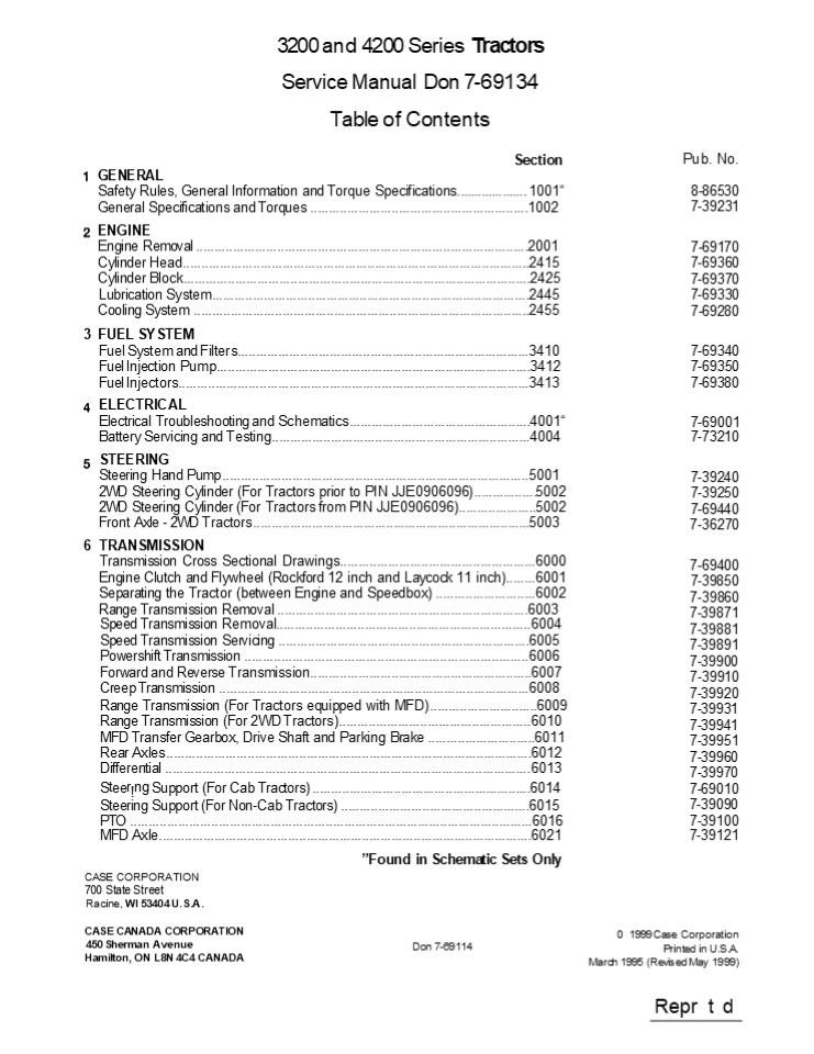
3200 and 4200 Series Tractors Service Manual Don
7-69134 Table of Contents Section
Pub. No.
GENERAL
Safety Rules, General Information and Torque
Specifications.................... 1001
8-86530 7-39231
General Specifications and Torques
..................................................
.........1002 ENGINE Engine Removal
..................................................
........................................2001 Cylin
der Head..........................................
..................................................
..2415 Cylinder Block.............................
..................................................
...............2425 Lubrication
System............................................
..........................................2445 Coo
ling System ......................................
..................................................
...2455 3 FUEL SYSTEM Fuel System and
Filters...........................................
....................................3410 Fuel
Injection Pump....................................
.................................................3
412 Fuel Injectors................................
..................................................
.............3413 ELECTRICAL Electrical
Troubleshooting and Schematics....................
.............................4001 Battery
Servicing and Testing.............................
.........................................4004 STEE
RING Steering Hand Pump ..........................
..................................................
.......5001 2WD Steering Cylinder (For Tractors
prior to PIN JJE0906096).................5002 2WD
Steering Cylinder (For Tractors from PIN
JJE0906096).....................5002 Front Axle -
2WD Tractors......................................
.....................................5003 6
TRANSMISSION Transmission Cross Sectional
Drawings..........................................
...........6000 Engine Clutch and Flywheel
(Rockford 12 inch and Laycock 11
inch)........6001 Separating the Tractor (between
Engine and Speedbox) ...........................60
02 Range Transmission Removal ....................
................................................60
03 Speed Transmission Removal.....................
................................................60
04 Speed Transmission Servicing
..................................................
..................6005 Powershift Transmission
..................................................
...........................6006 Forward and
Reverse Transmission..............................
..............................6007 Creep
Transmission .....................................
...............................................600
8 Range Transmission (For Tractors equipped with
MFD).............................6009 Range
Transmission (For 2WD Tractors)...................
.................................6010 MFD
Transfer Gearbox, Drive Shaft and Parking Brake
.............................6011 Rear
Axles.............................................
..................................................
....6012 Differential ............................
..................................................
.....................6013
7-69170 7-69360 7-69370 7-69330 7-69280
7-69340 7-69350 7-69380
7-69001 7-73210
7-39240 7-39250 7-69440 7-36270
7-69400 7-39850 7-39860 7-39871 7-39881 7-39891 7-
39900 7-39910 7-39920 7-39931 7-39941 7-39951 7-39
960 7-39970 7-69010 7-39090 7-39100 7-39121
Steer!ng Support (For Cab Tractors)
..................................................
.........6014
Steering Support (For Non-Cab Tractors)
..................................................
.6015 PTO ........................................
..................................................
...................6016
MFD Axle..........................................
..................................................
.........6021 Found in Schematic Sets Only CASE
CORPORATION 700 State Street Racine, WI 53404
U.S.A.
CASE CANADA CORPORATION 450 Sherman
Avenue Hamilton, ON L8N 4C4 CANADA
0 1999 Case Corporation Printed in U.S.A. March
1995 (Revised May 1999)
Don 7-69114
Repr t d
2
- BRAKES
- Parking Brake (For 2WD Tractors)..................
............................................7001
Rear Brakes (For Tractors prior to PIN
JJE0908037) .................................7002 - Rear Brakes (For Tractors from PIN JJE0908037)
.....................................7002 Brake
Master Cylinder...................................
..............................................7003
- HYDRAULICS
- Hydraulic Troubleshooting and Schematic...........
.......................................8001 - Hydraulic Hitch Adjustments ......................
.................................................8
005 - Multi Control Valve and Hydraulic
Pump..............................................
.......8010 - Unloading and Flow Control Valve..................
............................................8015
Remote Valves.....................................
..................................................
..... 8025 - Hydraulic Housing Servicing ......................
.................................................8
035 - Hydraulic Housing Removal.........................
...............................................
8040 - Differential Lock Cylinder and Solenoid Valve
............................................8060 - CHASSIS AND MOUNTED EQUIPMENT
- Pedal, Lever and Switch Adjustments...............
..........................................9001 - Air Conditioner Troubleshooting
- for Systems with RFC-134a Refrigerant (Visual and
Operating) ............ 9002 Air Conditioner
System Gauges and Testing - for Systems with RFC-134a Refrigerant
.................................................9
003 - Air Conditioner System Service
- for Systems with RFC-134a Refrigerant
.................................................9
004 - Air Conditioner System Component Servicing
7-39980 7-39990 7-69450 7-39130
7-39730 7-39140 7-39150 7-39160 7-39180 7-39190 7-
69260 7-39220
7-39742
7-69031
7-69041
7-39001
for Systems with RFC-134a Refrigerant .................................................9005 7-39010
XL Cab Removal .........................................................................................9006 7-39040
Low Profile Cab Removal............................................................................9007 N/A
Seat Platform and Fenders .........................................................................9008 7-39060
XL Cab Servicing ........................................................................................9009 7-39070
Hood and Panels.........................................................................................9011 Found in Schematic Sets Only 7-69270
7-69260
Don 7-69114
Issued 5-99
3
Section
1001
SAFETY, GENERAL INFORMATION AND TORQUE
SPECIFICATIONS
Printed in England June 1989
Don 8-86530
CASE CORPORATION
4
https//www.ebooklibonline.com Hello dear
friend! Thank you very much for reading. Enter
the link into your browser. The full manual is
available for immediate download. https//www.ebo
oklibonline.com
5
1001-5
GENERAL INFORMATION GEARS
CLEANING
Clean all metal parts except bearings, in mineral
spirits or by steam cleaning. Do not use caustic
soda for steam cleaning. After cleaning dry, and
put oil on all parts. Clean oil passages with
compressed air. Clean bearings in kerosene, dry
the bearings completely and put oil on the
bearings.
Check all gears for wear and damage. Replace
gears that have wear or damage.
OIL SEALS, O-RINGS AND GASKETS
Always install new oil seals, o-rings and
gaskets. Put petroleum jelly on seals and o-rings.
INSPECTION
SHAFTS
Check all parts when the parts are disassembled.
Replace all parts that have wear or damage. Small
scoring or grooves can be removed with a hone or
crocus cloth. Complete visual inspection for
indications of wear, pitting and the replacement
of parts necessary will prevent early failures.
Check all shafts that have wear or damage. Check
the bearing and oil seal surfaces of the shafts
for damage.
SERVICE PARTS
Always install genuine Case service parts, when
ordering refer to the Parts Catolog for the
correct part number of the genuine Case
replacement items. Failures due to the use of
other than genuine Case replacement parts are not
covered by warranty.
BEARINGS
Check bearings for easy action. If bearings have
a loose fit or rough action replace the bearing.
Wash bearings with a good solvent or kerosene and
permit to air dry. DONOT DRY BEARINGS WITH
COMPRESSED AIR.
LUBRICATION
NEEDLE BEARINGS
Only use the oils and lubricants specified in the
Operator's or Service Manual. Failures due to the
use of non specified oils and lubricants are not
covered by warranty.
Before you press needle bearings in a bore always
remove any metal protrusions in the bore or edge
of the bore. Before you press bearings into
position put petroleum jelly on the inside and
outside diameter of the bearings.
Issued 6-89 Primed iñ England
6
1001-6 STANDARD TORQUE DATA FOR NUTS AND
BOLTS Where no special torque data is specified,
the following torque figures should be applied.
Threads should be lubricated with engine oil or
chassis grease.
TOROUE SPECIFICATIONS 10O4 TOROUE SPECIFICATIONS 10O4 TOROUE SPECIFICATIONS 10O4 TOROUE SPECIFICATIONS 10O4 TOROUE SPECIFICATIONS 10O4 TOROUE SPECIFICATIONS 10O4 TOROUE SPECIFICATIONS 10O4 TOROUE SPECIFICATIONS 10O4 TOROUE SPECIFICATIONS 10O4 TOROUE SPECIFICATIONS 10O4
SIZE GRADE 8.8 GRADE 8.8 GRADE 8.8 GRADE 10.9 GRADE 10.9 GRADE 10.9 GRADE 12.9 GRADE 12.9 GRADE 12.9
SIZE lb-ft Nm kg/m lb-ft Nm kg/m lb-ft Nm kg/m
5 mm 4 5.5 0.56 5.5 7.5 0.76 6.6 9 0.92
0 mm 6.6 9 0.92 9.2 12.5 1.27 11 15 1.53
8 mm 16.5 22.5 2.3 23 31.5 3.2 26.5 36 3.67
10 mm 32 44 4.5 45 62 6.3 55 75 7.65
12 mm 57 77.5 7.9 81 110 11.2 95 130 13.2
14 mm 88 120 12.2 125 170 17.3 155 210 21.4
16 mm 140 190 19.4 195 265 27 236 320 32.6
18 mm 192 260 26.5 269 365 37.2 320 435 44.3
20 mm 273 370 37.7 383 520 53 457 620 63.2
22 mm 369 500 51 516 700 71.4 619 840 85.6
24 mm 471 640 65.2 665 900 92 796 1080 110
27 mm 702 950 97 996 1350 137.7 1195 1620 165.2
30 mm 955 1300 132.5 1328 1800 183.6 1593 2160 220.3
Issued 6-89 Printed in England
7
1001-7
TORQUE DATA FOR HYDRAULIC FITTINGS
FITTINGS, CONNECTIONS AND PLUGS
Diameter x Pitch Newton / Metres Pounds / Feet Kilogram / Metres
10 mm x 1 20 14.5 2
12 mm x 1.5 35 26 3.6
14 mm x 1.5 45 33.2 4.6
16 mm x 1.5 60 44 6.1
18 mm x 1.5 70 51 7.1
22 mm x 1.5 100 73 10.2
27 mm x 2 200 147 20.4
33 mm x 2 280 207 28.6
42 mm x 2 380 281 38.8
NUTS FOR TUBES AND HOSES
Diameter x Pitch Newton / Metres Pounds / Feet Kilogram / Metres
16 mm x 1.5 20 14.5 2
18 mm x 1.5 35 26 3.6
20 mm x 1.45 45 33.2 4.6
24 mm x 1.5 60 44 6.1
FLANGES
Diameter x Pitch Newton / Metres Pounds / Feet Kilogram / Metres
8 mm x 1.5 28 21 2.9
10 mm x 1.5 55 41 5.6
12 mm x 1.75 90 67 9.2
14 mm x 2 145 107 14.8
16 mm x 2 230 170 23.5
Don 8-86530
Issued 6-89
Printed in England
8
Section
1002 GENERAL SPECIFICATIONS AND TORQUES
CASE CORPORATION 700 State Street Racine, Wi
53404 U.S.A. CASE CANADA CORPORATION 3350 South
Service Road Burlington, ONL7N 3M6 CANADA
1995 Case Corporation Printed in U.S.A. March 1995
Don 7-39231
9
1002-2
TABLE OF CONTENTS GENERAL SPECIFICATIONS Capacitie
s ...............................................
..................................................
..................................................
........ 2 Engine Specifications
..................................................
..................................................
...................................... 3 Fuel
Specifications ...................................
..................................................
..................................................
....... 8 Steering Specifications ...... ........
.. ... ........ .......... . ............... ....
....... . . ... ... .... ..... . ... . . ... ..
... ..... 9 Transmission Specifications ......
.... . ...... ..... . .. .. . . . ...
............ ... .. . ..... . . . ....... .. . .
.. . ... . ...... .... . . 9 Brake Specifications
..................................................
..................................................
......................................
10 Hydraulic Specifications ......................
..................................................
..................................................
.......... 11 Air Conditioner Specifications
..................................................
..................................................
....................... 13 SPECIAL TORQUES
..................................................
..................................................
......................................... 14
GENERAL SPECIFICATIONS
- Capacities
- Coolant Capacity
- Cylinder Engines .................................
............................................ 11.4
litres - Cylinder Engines .................................
............................................ 13.7
litres - Engine Oil Capacity
- D-155, D-179 Engine ..............................
........... Without filter change 7.0 litres - With filter change 7.5 litres D-206 Engine
..................................................
... Without filter change 9.0 litres - With filter change 9.5 litres D-239, D-246,
D-268, DT-268 Engine ................ Without
filter change 9.3 litres - With filter change 9.8 litres
- Transmission/Hydraulic System Capacity
- 2WD ..............................................
..................................................
..... 34 litres - MFD ..............................................
..................................................
.. 36.5 litres - MFD Axle
- Differential .....................................
..................................................
.... 5.0 litres - Planetaries ......................................
..................................................
.. 0.6 litres - Fuel Tank
- Tractor with Cab .................................
.................................................
112 litres - Tractor without Cab ..............................
................................................
77 litres - Front PTO ........................................
..................................................
.... 0.65 litres
3.0 U.S. gal 3.6 U.S. gal
1.8 U.S. gal 2.0 U.S. gal 2.4 U.S. gal 2.5 U.S.
gal 2.5 U.S. gal 2.6 U.S. gal
9.0 U.S. gal 9.6 U.S. gal
1.3 U.S. gal 0.2 U.S. gal
29.6 U.S. gal 20.3 U.S. gal 0.2 U.S. gal
Don 7-39231
Issued 3-95
10
1002-3
Engine Specifications CYLINDER HEAD Cylinder Head
Maximum Warpage ..................................
........................ 0.12 mm Cylinder Head
Thickness New ....................................
.................................................
98.81 to 99.31 mm Minimum After Machining
..................................................
......... 98.54 mm
0.0047 inch
3.8902 to 3.9098 inch 3.8795 inch
NOTE The maximum amount of material that can be
machined from the cylinder head face is 0.T7 mm
(0.030 inch).
Inlet Valve Stem Diameter ........................
............................... 9.935 to 9.945
mm Exhaust Valve Stem Diameter ...................
.............................. 9.995 to 9.965
mm Maximum Stem Clearance in Guide Before
Reconditioning ................... 0.15 mm Valve
Clearance (Engine Warm) Inlet and Exhaust
................................. 0.30 mm
0.3912 to 0.3915 inch 0.3920 to 0.3924 inch 0.006
inch 0.012 inch
Valve Seat Angle .................................
..................................................
..................................................
............ 45
Distance of Cylinder Head Face to Valve
Face Inlet .......................................
..................................................
1.00 to 1.40 mm Exhaust .........................
..................................................
........ 1.20 to 1.60 mm Valve Guides Outside
Diameter .........................................
................... 16.060 to 16.078 mm Inside
Diameter .........................................
.......................... 9.865 to 9.901
mm Inside Diameter (Reamed) ......................
............................ 10.00 to 10.02
mm Distance from Top of Valve Guide to the Seat
in Cylinder for Valve Rotator ....................
................................... 28.0 mm Valve
Seat Insert Thickness ............................
........................................ 8.75
mm Valve Seat Outside Diameter Standard
..................................................
............................ 42.07 to 42.09
mm 0.006 inch (0.15 mm) Oversize
........................................... 42.22
to 42.24 mm 0.016 inch (0.40 mm) Oversize
........................................... 42.47
to 42.49 mm Minimum Valve Seat Contact Width
..................................................
...... 1.50 mm Cylinder Head Counterbore Diameter
for Valve Seat Insert Standard ...................
..................................................
..... 42.000 to 42.020 mm 0.006 inch (0.15 mm)
Oversize .......................................
42.150 to 42.170 mm 0.016 inch (0.40 mm) Oversize
....................................... 42.400 to
42.420 mm Counterbore Depth from Cylinder Head
Face ......................... 12.24 to 12.29 mm
Valve Springs Free Length ........................
..................................................
54.00 /- 1.50 mm Rocker Shaft Outside Diameter
...............................................
21.56 to 21.59 mm Rocker Arm Bushing Diameter
................................................
21.62 to 21.64 mm Rocker Shaft Spring
..................................................
............ 21.671 to 21.63 mm Free Length
..................................................
..................................... 37.70
mm Push Rods Effective Length D-155, D-206
..................................................
..................176.50 to 177.00 mm D-179,
D-239, D-246 .....................................
................... 211.00 to 211.50 mm D-268,
DT-268 ...........................................
.......................216.50 to 217.00 mm
0.04 to 0.05 inch 0.047 to 0.06 inch
0.6323 to 0.6330 inch 0.3883 to 0.3893
inch 0.3940 to 0.3945 inch
1.102 inch 0.344 inch
1.656 to 1.657 inch 1.662 to 1.663 inch 1.672 to
1.673 inch 0.059 inch
1.653 to 1.654 inch 1.659 to 1.660 inch 1.669 to
1.670 inch 0.482 to 0.484 inch
2.125 /- 0.059 inch 0.848 to 0.850 inch 0.851 to
0.852 inch 0.850 to 0.851 inch 1.484 inch
6.949 to 6.968 inch 8.307 to 8.326 inch 8.524 to
8.543 inch
Don 7-39231
Issued 3-95
11
1002-4 PISTONS
B
2425P1 Piston Clearance in Cylinder Liner
measured 90 degrees to Piston Pin Hole Diameter
A measured at a Height of 4.0 mm (0.157 inch)
...... 0.09 to 0.13 mm Diameter B measured at a
Height of 50.0 mm (1.968 inch) .... 0.15 to 0.20
mm Diameter of Piston Pin Hole C D-155, D-179,
D-206, D-239, D-246, D-268 ...................
35.997 to 36.002 mm
0.0035 to 0.0050 inch 0.0059 to 0.0079 inch
1.4172 to 1.4174 inch
DT-268 ...........................................
............... 38.00 mm ( 0.002 - 0.003) 1.4960
inch( 0.00007 - 0.0001)
Piston Ring Gap Compression Rings
..................................................
............... 0.35 to 0.55 mm Oil Control Ring
..................................................
.............. 0.25 to 0.40 mm
0.014 to 0.022 inch 0.010 to 0.016 inch
Piston Pin Diameter D-155, D-179, D-206,D-239,
D-246, D-268 .................... 35.987 to
35.991 mm DT-268 .................................
...........................................
37.987 to 37.991 mm
1.4168 to 1.4170 inch 1.4955 to 1.4957 inch
Protrusion of Pistons D-155, D-206 Engines (with
a 111.1 mm Stroke) .................... 0.32 to
0.70 mm D-179, D-239 Engines (with a 128.52 mm
Stroke) ................. 0.36 to 0.74 mm D-268,
DT-268 Engines (with a 139.77 mm Stroke)
............... 0.36 to 0.74 mm
0.0126 to 0.027 inch 0.0141 to 0.029 inch 0.0141
to 0.029 inch
CONNECTING RODS
Dimension A D-155, D-206 .........................
.......................................... 187.96
to 188.01 mm D-179, D-239, D-246, D-268, DT-268
............................. 213.84 to 213.89
mm Dimension B D-155, D-179, D-206, D-239, D-246,
D-268 ................... 36.012 to 36.022 mm
DT-268 ...........................................
................................. 38.026 to
38.036 mm Dimension C ............................
..................................................
................ 4.0 mm Connecting Rod to
Crankshaft Side Clearance ........................
... 0.16 to 0.25 mm
7.400 to 7.402 inch 8.419 to 8.421 inch
1.4178 to 1.4182 inch 1.4970 to 1.4974 inch 0.16
inch 0.006 to 0.010 inch
Issued 3-95
Don 7-39231
12
1002-5
CYLINDER LINERS
Dimension A D-155, D-179, D-206, D-239
...................................... 98.425 to
98.449 mm D-246, D-268, DT-268 ...................
................................... 100.00 to
100.24 mm Dimension B D-155, D-206
..................................................
...................................... 200 mm
D-179, D-239, D-246, D-268, DT-268
..................................................
.215 mm Dimension C ..............................
..............................................
7.700 to 7.715 mm Dimension D ....................
..................................................
....................... 119 mm Cylinder Liner
Protrusion .......................................
...................... 0.08 to 0.12 mm Maximum
Warpage of Surface ...............................
................................. 0.04 mm O-Ring
Groove Diameter (New) Golden Tracers
..................................................
... 118.32 to 118.58 mm (Old) Red Tracers
..................................................
... 118.54 to 118.80 mm
3.8750 to 3.8759 inch 3.9370 to 3.9379 inch
7.874 inch 8.464 inch 0.3031 to 0.3037 inch 4.685
inch 0.0031 to 0.0047 inch 0.0016 inch
4.658 to 4.668 inch 4.667 to 4.677 inch
BALANCER (4 Cylinder Engines only) Backlash
Balancer Drive Gear to Crankshaft Gear D-206,
D-239, D-246 .....................................
.......................0.25 to 0.40 mm D-268,
DT-268 ...........................................
..........................0.23 to 0.50
mm Backlash Balancer Gear ........................
.................................. 0.18 to 0.23 mm
0.010 to 0.016 inch 0.009 to 0.020 inch 0.007 to
0.009 inch
CYLINDER BLOCK Cylinder Block Surface Maximum
Warpage .........................................0
.12 mm Cylinder Block Surface Height from
Centerline of Crankshaft D-155, D-206
..................................................
........ 309.842 to 309.908 mm D-179, D-239,
D-246 ............................................
... 344.386 to 344.462 mm D-268, DT-268
..................................................
....... 353.386 to 353.462 mm
0.0047 inch
12.198 to 12.201 inch 13.558 to 13.561
inch 13.912 to 13.915 inch
CRANKSHAFT Crankshaft Journals and
Crankpins Maximum Out of Round per 25mm (1 inch)
...................................... 0.004
mm Maximum Taper per 25 mm (1 inch)
...............................................
0.004 mm Crankshaft Rear Sealing Flange Permitted
Run-out ..........................................
............................ 0.050 mm Permitted
Out of True ......................................
.................................. 0.020
mm Crankshaft Main Bearing Clearance (New
Inserts) ................... 0.070 to 0.14 mm
Crankshaft End Float .............................
...................................... 0.15 to
0.23 mm Connecting Rod Bearing Clearance (New
Inserts) ...................... 0.06 to 0.12 mm
Crankshaft Balancer Ring Gear to Drive Weight
Gear Backlash D-206, D-239, D-246
..................................................
..............0.25 to 0.40 mm D-268, DT-268
..................................................
........................0.23 to 0.50 mm
0.00015 inch 0.00015 inch
0.002 inch 0.00078 inch 0.00275 to 0.00551
inch 0.006 to 0.009 inch 0.0023 to 0.0047 inch
0.010 to 0.016 inch 0.009 to 0.020 inch
Don 7-39231
Issued 3-95
13
Sectinn 2001
ENGINE REMOVAL
CASE CORPORATION 700 State Street Racine, Wi
53404 U.S.A.
CASE CANADA CORPORATION 3350 South Service Road
Burlington, ONL7N 3M6 CANADA
0 1994 Case Corporation Printed in U.S.A.
Decerrber 1994
Don 7-69170
14
2001-2
TABLE OF CONTENTS ENGINE Removal and Installation
(all models) .....................................
..................................................
......................... 2 Engine Removal
(Tractors with Cab) ..............................
..................................................
.............................. 3 Engine Removal
(Tractors without Cab) ...........................
..................................................
............................ 4
ENGINE
Removal and Insallation (all models) STEP 1 Park
the machine on hard level ground, apply the
parking brake and stop the engine. Put blocks in
front of and behind the rear wheels.
STEP 7
STEP 2 Remove the Hood and Side Panels, refer to
Section 9011.
Disconnect and cap the hydraulic steering tubes
(1).
STEP 3 Disconnect the battery, negative (-)
terminal first.
STEP 8 NOTE For Installation, connect the
positive () terminal first. NOTE For Tractors
without Cab, remove the battery. STEP 4 Remove
the radiator, refer to Section 2455. STEP 5 Strip
away the Air Conditioning Components (if
equipped), refer to Section 9005.
Install two 5/8 x 2 1/2 inch UNC bolts into each
side Of the front bolster.
STEP 6
If the tractor is equipped with MFD, remove the
MFD Drive Shaft, refer to Section 6011.
STEP 9
Install wooden wedges between the front axle and
front bolster.
Don 7-69170
Issued 12-94
15
2001-3
STEP 10
STEP 13
Attatch suitable lifting equipment to the front
bolster. Support the front of the engine using
suitable stands. Remove the front bolster
retaining bolts.
Disconnect the engine harness (1) and the
steering support ground cable (2) from the
steering support. Disconnect the circuit breaker
(3) from the cab harness Put identification marks
on the hydraulic steering hoses (4) and (5).
Disconnect and cap the hoses and tubes.
STEP 11 Raise the front of the engine to allow
clearance for the front pulley and carefully move
the front bolster and front axle from the engine.
STEP 14
NOTE Move the front bolster and front axle away
from the engine, carefully support the complete
assembly on suitable stands. Engine Removal
(Tractors with Cab) NOTE For Tractors without
Cab, reler to Step 21. STEP 12 Disconnect the
cab harness ground cable (1) and the fuel return
tube (2). Disconnect the bracket (3) from the
inlet manifold and remove the hydraulic steering
tubes.
Disconnect the engine stop control cable (1) and
the throttle control cable (2) from the fuel
pump. Remove the tie strap (3) from the engine
stop control cable and battery cable. NOTE For
Installation, refer to Section 9001 for cable
adjustment.
Don 7-69170
Issued 12-94
16
2001-4 STEP 15
STEP 19 Attatch suitable lifting equipment to the
engine. Support the front of the Speed
Transmission using suitable stands. Remove the
clutch housing bolts.
STEP 20 Make sure all parts are disconnected and
remove the engine assembly.
NOTE Before connecting the Engine and Speed
Transmission, lubricate the splines of the
friction plate and the pressure plate with
MOLYKOTE D321R or equivalent.
Disconnect and cap the fuel supply tube (1).
Remove the cover (2) and disconnect the wiring
connections from the starter motor.
NOTE For Installation, follow the same procedure
in reverse order.
NOTE For Tractors with 3 cylinder engines, the
fuel su ply tube is located on the RH side of the
engine. ST? 16 Disconnect the engine heater hoses
(both sides).
Engine Removal (Tractors without Cab) STEP 21
STEP 17
Disconnect the tachometer cable from the engine
timing cover. Remove the cab floor mat and the
floor inspection plate. STEP 18 Install a
suitable lifting eye into the rear engine
mounting hole.
Don 7-69170
Issued 12-94
17
2001-5
STEP 22
STEP 25 Remove the down swept exhaust, (if
equipped).
STEP 26
Disconnect the engine stop control cable (1),
fuel return tube (2) and fuel supply tube (3).
NOTE For Tractors with 3 cylinder engines, the
fuel supply tube (3) is located on the RH side of
the engine.
Remove the split pin and disconnect the throttle
linkage (1). Disconnect the ground cable (2).
STEP 27 Attatch suitable lifting equipment to the
engine. Support the front of the Speed
Transmission using suitable stands. Remove the
clutch housing bolts.
NOTE For Installation, install the engine stop
control cable (I), refer to Section 9001 for
cable adjustment.
STEP 23
STEP 28 Make sure all parts are disconnected and
remove the engine assembly. NOTE Before
connecting the Engine and Speed Transmission,
lubricate the splines of the friction plate and
the pressure plate with MOLYKOTE D32IR or
equivalent.
NOTE For Installation, fo/low the same procedure
in reverse order.
Remove the cover (1) and disconnect the
electrical wiring from the starter motor. Put
identification marks on the hydraulic steering
hoses (2) and (3). Disconnect and cap the
hoses and tubes. Disconnect the bracket (4)
from the inlet manifold and remove the hydraulic
steering tubes.
STEP 24 Label and disconnect the wiring harness
connections from the horn and engine components.
Move the harness clear of the engine.
Don 7-69170
Issued 12-94
18
2415-5
CYLINDER HEAD
Removal and Insallation NOTE The Removal and
Installation procedure is the same for both 3 and
4 cylinder engines unless otherwise stated.
STEP 5 Remove the air filter assembly and
disconnect the thermostart from the inlet
manifold.
NOTE For tractors with ether start, remove the
ether start system.
NOTE Some of the following Sieps show the engine
removed from the machine. This is for
photographis purposes only.
STEP 6
STEP 1 Park the machine on hard, level ground,
apply the parking brake and stop the engine. Put
blocks in front of and behind the rear
wheels. STEP 2 Disconnect the baxery, negative
(-) terminal first. NOTE For Installation,
connect the positive () terminal first.
Disconnect, cap and remove the high pressure
tubes (1) from the injection pump and injectors.
Disconnect and cap the injector spill line (2) at
the tee fitting (3).
STEP 3 Remove the Hood and Side Panels, refer to
Section 9011.
NOTE ror Installation, tighten the high pressure
tubes (I) to a torque of 50 to 70 Nm (36 to 51 lb
ft).
STEP 4 Put a suitable container under the engine.
Remove the plug from the cylinder block and drain
the coolant.
Hot coolant can spray out when the radiator
filler cap or drain plugs are removed. First
allow the system to cool then turn the filler cap
to the first notch and wait until the pressure is
released.
NOTE For Installation, fill the radiator with
coolant to the correct level, start the engine
and run at half throttle for 10 minutes. Stop the
engine. Check for and repair any leaks. Check the
coolant level in the radiator and add coolant if
necessary.
Disconnect the spill return fitting from the side
of the injectors. Remove and discard the copper
washers from both sides of the fitting. NOTE For
Installation, install new copper washers on both
sides of the fitting. Install the fitting and
tighten to a torque of 2 to 8 Nm (1.5 to 6 lb ft).
Never operate the engine in a closed building.
Proper ventilation is required under all
circumstances.
Don 7-69360
Issued 12-94
19
2415-6 STEP 8 For tractors without cab,
disconnect the tachometer cable from the engine
timing cover.
STEP 11
STEP 9
Remove the rocker shaft assembly from the
cylinder head and remove the push rods.
NOTE For Installation, make sure the punch mark
on the end of the rocker shaft is aligned with
the slot in the front rocker arm support bracket
(refer to Step 50), make sure the push rods
locate into the ends of the rocker arm adjusting
screws. Tighten the rocker shaft retaining bolts
to a torque of 60 to 70 Nm (44 to 51 lb ft). If
the bolts cannot be located into the cylinder
head, loosen the clamping bolts on the rocker
shaft support brackets. Tighten the clamping
bolts after installing the rocker shaft retaining
bolts.
Disconnect the breather (1) from the rocker
cover. Remove the exhaust elbow (2). Remove the
rear tube (3) from the coolant filter conditioner
and remove the filter bracket. Remove the brake
tube support bracket (4), loosen the clips on the
coolant hose (5) at the water manifold.
STEP 10
NOTE For Installation, adjust the inlet and
exhaust valve clearances to 0.30 mm (0.012 inch)
in the sequences shown below. 4 CYLINDER ENGINE
1 2 3 4 5 6 7 8
Put number 1 piston at T.D.C on the qqmpressien
stroke and adjust valves 1, 2, 4 and 5.
Remove the rocker cover and discard the gasket.
Put number 4 piston at T.D.C on the cqljjptes8ton
stroke and adjust valves 3, 6, 7 and 8.
NOTE For Installation, install a new rocker
cover gasket and ru6ber sealing washers on the
rocker cover retaining bolts. Tighten the bolts
to a torque of 20 to 27 Nm (15 to 20 lb fi).
3 CYLINDER ENGINE
1 2 4 5
3 6
Put number 1 piston at T.D.C on the qppjptegqtofj
stroke and adjust valves 1, 2, 4 and 5.. Put
number 1 piston at T.D.C on the e/haqst stroke
and adjust valves 3 and 6.
Don 7-69360
Issued 12-94
20
2415-7
STEP 12 Remove the cylinder head retaining
bolts. NOTE For Installation, the cylinder head
öolts are two different lengths. The l27 mm (5
inch) öo/ls are positioned along the outer rows
and the 146 mm (5.75 inch ) bolts are positioned
along the inner rows. Tighten the cylinder head
bolts in three stages in the sequence shown 4
CYLINDER ENGINE
STEP 13 Install suitable lifting equipment and
remove the cylinder head, put the cylinder head
assembly onto a clean work bench. Remove and
discard the cylinder head gasket.
NOTE For Installation, install the cylinder head
gasket, make sure the cylinder head locates on
the two c/one/s in the cylinder 6lock.
STEP 14 Use compressed air to remove dirt and
dust from the cylinder bores and bolt holes. Make
sure the cylinder block and head surfaces are
clean and free of old gasket material.
12 O
14 y 0 O
6 4 O y 0 O
10 O
s O
16 O
O
o
o
o
O " o
17
o
o
o
NOTE For Installation, fo/los the same procedure
in reverse order.
4
3
5
13
3 CYLINDER ENGINE
5
3 O
13 O
O
1st Stage ........................ 50 Nm 2nd
Stage ...................... 100 Nm 3rd Stage
....................... 150 Nm
(37 lb ft) (74 Ib ft) (110 Ib ft)
Don 7-69360
lssued 12-94
21
2415-8 Disassembly and Assembly
NOTE Items are numbered in order of Disassembly,
Assembly is in reverse order of Disassembly.
- MANIFOLD INLET
- GASKET
- MANIFOLD EXHAUST
- GASKET
- MANIFOLD COOLANT
- GASKET
- BOLT
- RETAINER
- INJECTOR
- COLLET
- VALVE SPRING RETAINER
- VALVE SPRING
- VALVE STEM SEAL
- t4. VALVE SPRING SEAT
- VALVE EXHAUST
- VALVE INLET
STEP 15 Remove the inlet manifold (1) gasket (2).
STEP 17 Remove the coolant manifold (5) and
discard the gasket (6).
and discard the
NOTE For Installation, apply sealant B17555 and
install a new gasket (2). Install the inlet
manifold bolts and tighten to a torque of 35 to
40 Nm (25 to 29 lb ft).
NOTE For Installation, apply sealant B17555
and install a new gasket (6).
STEP 18 Remove the bolt (7) and retainer (8).
Remove the injector (9). Repeat the procedure to
remove the remaining injectors.
STEP 16 Remove the exhaust manifold (3) and
discard the gasket (4).
NOTE For Installation, install a new o-ring onto
the injector (9).
NOTE For /nsta/lation, install a new gasket (3).
Install the exhaust manifold nuts and tighten to
a torque of 35 to 40 Nm (25 to 29 lb ft).
Don 7-69360
Issued 12-94
22
2415-9
STEP 24
STEP 19 Mark the heads of the valves for easy
assembly. Install the valve spring compressor and
compress the valve spring (12).
STEP 20 Remove the two collets (10) from the
valve spring retainer (11), remove the valve
spring retainer (11). Remove the valve spring
(12).
2415CH Check the cylinder head surface for
warpage using a straight edge and feeler gauge in
the positions shown.
STEP 21 Remove and discard the valve stem seal
(13). Remove the valve spring seat (14).
IMPORTANT If the warpage is more than D.12 mm
(0.04T inch) the cylinder head must 6e machined
or replaced. Refer to Specifications on Page 3.
NOTE For Installation, install a new valve stem
seal (13), push the seal down the stem until it
locates in the groove of the valve guide.
STEP 25 Measure the height of the cylinder head.
Replace the cylinder head if the height is less
than 98.54 mm (3.8795 inch).
STEP 22 Remove the valve (15) and (16) from the
cylinder head. Repeat the procedure to
remove the remaining valves. The following valve
removal sequence is from the front of the engine
NOTE The maximum amount of material that can be
machined from the cylinder head is 0.77 mm (0.030
inch).
4 CYLINDER ENGINE 1 2 3 4 5 6 7 8 exhaust, inlet,
exhaust, inlet, exhaust, inlet, exhaust, inlet.
STEP 26
3 CYLINDER ENGINE 1 2 3 4 5 6 exhaust, Inlet,
exhaust, inlet, exhaust, Inlet. NOTE ror
Installation, lubricate the valve stems with
clean engine oil and install the valves into the
cylinder head.
Inspection STEP 23 Clean the cylinder head in
cleaning solvent and remove all traces of carbon
and old gasket materials.
SM1351
Measure the wear in the valve guide bore with a
bore gauge. Measure the wear in three positions
as shown. If the bore of the valve guide is more
than 10.17 mm (0.400 inch) the valve guide must
be replaced, refer to Page 10.
STEP 27 Measure the free length of the valve
springs. If the free length is less than 54 mm
(2.125 inch) replace the spring.
Don 7-69360
Issued 12-94
23
2415-10
VALVE GUIDES STEP 29
Removal and Installation STEP 28
Install the new valve guide with the special tool
3055699R1 until the special tool contacts the Cy
FldG.' hf3ad STEP 30 Install the valve guide
reamer, 04-478-1, and ream the bores of the
guides to a size of 10.00 to 10.02 mm (0.3940 to
0.03945 inch).
Use a bushing driver to remove the guide from the
cylinder head.
INLET AND EXHAUST VALVE
Inspection STEP 31 Use a wire brush to clean the
valves, care must be taken not to damage the
valve stems.
STEP 33
STEP 32
2415B
- Heavy Carbon and Varnish Deposits This condition
can be caused by - Worn valve guides and seats.
- Worn valve stem oil seals.
- Worn pistons and rings.
- Engine not reaching operating temperature.
Check the valves for the following conditions and
replace if necessary.
- 2415A
- Worn Valve Stems This condition can be caused by
- Restriction in oil supply to the rocker shaft.
- Excessive cylinder head temperatures.
- Operating the engine under extreme load
conditions.
Don 7-69360
Issued 12-94
24
2415-11
STEP 34
STEP 37
2415F
Worn Collet Grooves and Stem Tips Replace the
valve if either of the above conditions are
present.
2415C
- Rust or Pitting on Valve Stems This condition can
be caused by - Using poor grade lubricants and fuel.
- Failing to use an inhibitor to protect the
engine during long storage periods.
NOTE Also check the condition of the valve
spring retainer and collets. Replace if necessary.
STEP 28 The following is normal for both inlet
and exhaust valves.
STEP 35
2415D
Rust or Pitting on Valve Face This condition can
be caused by using poor grade fuel and lubricants.
2415G
Very fine pitting to the valve and seat faces. If
this condition is present it will not be
necessary to reface the valves or seats. Measure
the stems on the inlet and exhaust valves.
Replace the valves if the measurements are not
within the specifications.
STEP 36
STEP 39
2415E Deep Burns to Valve Face This condition can
be caused by 1. Running at excessive loads and
temperatures.
2. Grinding the valve face seat too narrow.
SMAZZ2 Measure the clearance from the face of the
valve to the face of the cylinder head. The
clearance must be
Inlet valve .. 1.0 to 1.4 mm (0.04 to 0.05
inch) Exhaust valve 1.2 to 1.6 mm (0.047 to 0.06
inch) NOTE If the measurement is more than
specified replace the valve and/or seat. If the
measurement is less than specified grind the
valve seat.
Don 7-69360
Issued 12-94
25
Suggest If the above button click is invalid.
Please download this document first, and then
click the above link to download the complete
manual. Thank you so much for reading
26
2415-12
EXHAUST VALVE SEAT STEP 41
Installation
NOTE If new valve seat inserts are required it
is recommended that you have a qualified enpine
shop machine the cylinder head to the following
Specifications. NOTE Replacement valve seat
inserts are available for exhaust valves only,
oversize in 0.15 mm (0.006 inch) and 0.40 mm
(0.015 Inch).
STEP 40 Machine the Cylinder Head to the
following Specifications for Valve Seat
Inserts Cylinder Head Counterbore Diameter for
Valve Seat Insert.
Put the valve seat inserts in dry ice until the
temperature falls to - 60C (- 76F). Install the
valve seat insert into the cylinder head Make
sure the valve insert is fully seated in the
cylinder head by using a bushing driver.
0.15 mm (0.006 inch) Oversize Insert 42.150 to 42.170 mm (1.659 to 1.660 inch)
0.40 mm (0.016 inch) Oversize Insert 42.400 to 42.420 mm (1.669 to 1.670 inch)
Always wear protective gloves or mittens when
handling frozen parts.
Counterbore Depth from Cylinder Head Face
12.24 to 12.29 mm (0.482 to 0.484 inch)
Valve Seat Outside Diameter
0.15 mm (0.006 inch) Oversize Insert 42.22 to 42.24 mm (1.662 to 1.663 inch)
0.40 mm (0.016 inch) Oversize Insert 42.47 to 42.49 mm (1.672 to 1.673 inch)
VALVE SEAT STEP 43
Refacing STEP 42
1.5 mm (0.059 inch) MI MUX
552740 Use a valve seat cutting tool and make
light cuts until the valve seat is within
specifications. If the width of the valve seat is
too wide, reduce the width with a 60' or 30
cutting tool. Apply engineers' blue to the valve
and check for correct seat contact. NOTE Minimum
valve seat contact width is 1.50 mm (0.059
inch). Don 7-69360
When the valve and seat contact are correct grind
the valves and seats with grinding compound.
Issued 12-94
27
https//www.ebooklibonline.com Hello dear
friend! Thank you very much for reading. Enter
the link into your browser. The full manual is
available for immediate download. https//www.ebo
oklibonline.com
Recommended

