

New Holland TS100A Tractor Service Repair Manual Instant Download PowerPoint PPT Presentation
Title: New Holland TS100A Tractor Service Repair Manual Instant Download
1
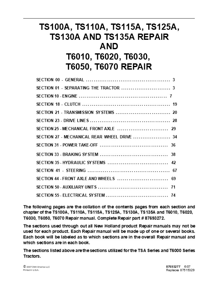
TS100A, TS110A, TS115A, TS125A, TS130A AND
TS135A REPAIR
AND
T6010, T6020, T6030, T6050, T6070 REPAIR SECTION
00 - GENERAL .....................................
....... 3 SECTION 01 - SEPARATING THE TRACTOR
.......................... 3 SECTION 10 - ENGINE
..............................................
7 SECTION 18 - CLUTCH ............................
.................. 19 SECTION 21 - TRANSMISSION
SYSTEMS ............................. 20 SECTION
23 - DRIVE LINES .................................
......... 28 SECTION 25 - MECHANICAL FRONT AXLE
........................... 29 SECTION 27 -
MECHANICAL REAR WHEEL DRIVE ....................
34 SECTION 31 - POWER TAKE-OFF
.................................... 36 SECTION
33 - BRAKING SYSTEM ..............................
...... 38 SECTION 35 - HYDRAULIC SYSTEMS
................................ 42 SECTION 41 -
STEERING .........................................
.. 67 SECTION 44 - FRONT AXLE AND WHEELS
........................... 69 SECTION 50 -
AUXILIARY UNITS ..................................
... 71 SECTION 55 - ELECTRICAL SYSTEM
................................. 74 The
following pages are the collation of the contents
pages from each section and chapter of the
TS100A, TS110A, TS115A, TS125A, TS130A, TS135A
and T6010, T6020, T6030, T6050, T6070 Repair
manual. Complete Repair part 87693272. The
sections used through out all New Holland product
Repair manuals may not be used for each product.
Each Repair manual will be made up of one or
several books. Each book will be labeled as to
which sections are in the overall Repair manual
and which sections are in each book. The
sections listed above are the sections utilized
for the TSA Series and T6000 Series Tractors.
? 2007 CNH America LLC Printed In U.S.A.
87693277 6/07 Replaces 87515329
2
Some sections of this Repair Manual have been
revised to include the New T6000 Delta and Plus
Series Models T6010, T6020, T6030, T6050, and
T6070.
Please note the following to locate new T6000
Tractor Model Repair information For complete
engine repair information for the new T6000
Series Tractors use Engine Repair Manual
87661796. Most all repairs can be carried out by
following the Tractors systems and specific
product configurations in the repair manual.
Example 16 x16 Transmission, Air Conditioning
and TSA Standard Series Closed Center Hydraulic
System. TSA Standard Repair Information also
applies to the New T6000 Delta Series Models.
Where specific T6000 Tractor Models are not
identified use the following TSA to T6000 cross
reference
T6000 Tractor Models T6010 T6020 T6030 T6050
T6070
Use TSA tractor Model TS100A TS110A TS115A
TS125A TS135A
2
3
INFORMATION
With the introduction of the T6000 Series
Tractors, controller identifications codes have
changed. Also, the location of the diagnostic
connector has changed. The updated Repair Manual
87693272 does not contain the new controller
IDs or the new location of the diagnostic
connector. This page shows the T6000 Series
controller identification codes and the
diagnostic connector location. NOTE Please
insert a copy of this page in the front of each
Repair Manual Volume for your reference.
Models covered are T6000 DELTA TRACTORS T6020,
T6030, T6050 T6000 PLUS SERIES TRACTORS T6010,
T6020, T6030, T6050, T6070 CONTROLLER
IDENTIFICATION CODES The controller identifiers
change with the introduction of the T6000 range
of tractors, eg., Controller DA for TS-A will
become Controller DR for T6000 range. This is
required to be remembered throughout this Repair
Manual. See table below
Identifier Identifier Controller Function(s)
TS-A T6000
DA DR 24x24 Transmission, Electronic Draft Control, Rear PTO, Differential Lock, Four Wheel Drive
DB DS 16x16 Transmission, Electronic Draft Control, Rear PTO, Differential Lock, Four Wheel Drive
DD DU (Options) Front PTO, Front Hitch, Front Axle Suspension, Electronic Hydraulic Remotes
EDC7 EDC16 Engine Control (Engine Side)
HA HJ Enhanced Analogue Digital Instrument Cluster (ADIC)
HB HK Basic ADIC
GA GA 12x12 PTO Controller - Rear PTO, Differential Lock, Four Wheel Drive
JA JA Keypad
? 2007 CNH America LLC Printed In U.S.A.
87693279
6/07
4
https//www.ebooklibonline.com Hello dear
friend! Thank you very much for reading. Enter
the link into your browser. The full manual is
available for immediate download. https//www.eb
ooklibonline.com
5
CONTROLLER FUNCTIONS
Electronic Module Electronic Module Electronic Module Electronic Module Electronic Module
Model/Type 24x24 16x16 24x24 16x16 12x12 24x24 16x16
Function DA(DR) DB(DS) DD(DU) GA EDC7 (EDC16)
Rear PTO 7 7 7
Differential Lock 7 7 7
Four Wheel Drive 7 7 7
Engine Control (vehicle side) 7 7
Auto Headland Turn Sequence (HTS) 7 7
Electronic Draft Control 7 7
Front Suspension 7
Front PTO 7
Front Lift 7
Electro-Hydraulic Remotes 7
Transmission 24x24 7
Transmission 16x16 7
Engine Control (engine side) 7
The controller type is identified by a code which
is attached to each module. The code, for
example, DB/DS identifies it as the module
used on a tractor with a 16x16 transmission
controlling those functions highlighted in the
table above. All the modules on the tractor are
linked by the CAN harness and this also links in
the instrument cluster, gear display (16x16
only) and diagnostic connector. Refer to the
system diagrams in Section 55, Chapter 1 of this
repair manual for full controller details and
inter connectivity. DIAGNOSTIC CONNECTORS
(ADDITIONAL C PILLAR LOCATION) A single
diagnostic port, 2, located behind the trim
under the transmission control levers, or on the
right hand C pillar, 1, to interrogate all of
the controllers is incorporated into the wiring
harness. With the aid of special service tool
380000843, the port can be used to gain access
to the on-board H-menu diagnostics, see Section
55, Chapter 1 of this Repair Manual for full
details, to download software or to connect in
more specialized diagnostic equipment such as
the E.S.T. (Electronic Service Tool).
6
SECTION 00 - GENERAL - CHAPTER 1
1
SECTION 00 - GENERAL Chapter 1 - General
Information CONTENT
Section 00 000
Description Page General Instructions
..................................................
.......... 2 Precautionary Statements
..................................................
..... 3 Health and Safety ........................
...................................... 7 Ecology
and the Environment ..............................
.................... 15 Product Identification
..................................................
....... 16 International Symbols
..................................................
....... 19 Specifications - Plus/Deluxe Models
............................................
20 General Dimensions ............................
.......................... 20 Specifications -
Standard Models ..................................
............ 27 General Dimensions
..................................................
.... 27 Minimum Hardware Tightening Torques
......................................... 34
7
2
SECTION 00 - GENERAL - CHAPTER 1
- GENERAL INSTRUCTIONS
- IMPORTANT NOTICE
- All maintenance and repair operations described
in this manual should be carried out exclusively
by authorised workshops. All instructions should
be carefully observed and special equipment where
indicated should be used. - Anyone who carries out service operations
described without carefully observing these
instructions will be directly responsible for
any damage caused. - NOTES FOR EQUIPMENT
- Equipment shown in this manual is
- designed expressly for use on these tractors
- necessary to make a reliable repair
- accurately built and strictly tested to offer
efficient and long- lasting working life. - NOTICES
- The words front, rear, right hand, and
left hand refer to the different parts as seen
from the operators seat oriented to the normal
direction of movement of the tractor.
8
PRECAUTIONARY STATEMENTS
SECTION 00 - GENERAL - CHAPTER 1 3
PERSONAL SAFETY Throughout this manual and on
machine decals, you will find precautionary
statements (DANGER, WARNING, and CAUTION)
followed by specific instructions. These
precautions are intended for the personal safety
of you and those working with you. Please take
the time to read them. DANGER This word DANGER
indicates an immediate hazardous situation that,
if not avoided, will result in death or serious
injury. The color associated with Danger is
RED. WARNING This word WARNING indicates a
potentially hazardous situation that, if not
avoided, could result in death or serious
injury. The color associated with Warning is
ORANGE. CAUTION This word CAUTION indicates a
potentially hazardous situation that, if not
avoided, may result in minor or moderate injury.
It may also be used to alert against unsafe
practices. The color associated with Caution is
YELLOW.
FAILURE TO FOLLOW THE DANGER, WARNING, AND
CAUTION INSTRUCTIONS MAY RESULT IN SERIOUS
BODILY INJURY OR DEATH. MACHINE SAFETY The
precautionary statement (IMPORTANT) is followed
by specific instructions. This statement is
intended for machine safety. IMPORTANT
IMPORTANT The word IMPORTANT is used to inform
the reader of something he needs to know to
prevent minor machine damage if a certain
procedure is not followed. INFORMATION NOTE
NOTE Instructions used to identify and present
supplementary information.
9
4 SECTION 00 - GENERAL - CHAPTER 1
IMPORTANT WARNINGS The machine is designed and
produced exclusively for agricultural use.
national, regional or local distributors, cannot
be held liable for damage resulting from the
malfunction of parts and/or components not
approved by CNH AMERICA LLC.
All other use will be considered to be contrary
to the use specified by CNH AMERICA LLC, who
cannot be held liable for damage to property or
the machine, or for personal injuries which may
result.
Under no circumstances will a guarantee be issued
for products made or sold by CNH AMERICA LLC
that are damaged as a result of the malfunction
of parts and/or components not approved by CNH
AMERICA LLC.
Persons who risk improper use will therefore
assume the responsibility for any consequences
arising from such use.
TO PREVENT ACCIDENTS Most accidents and personal
injuries taking place in workshops are due from
non-observance of some essential rules and
safety precautions.
Compliance with the instructions for use,
maintenance and repairs described in this manual,
are the essential preconditions for use
specified by CNH AMERICA LLC.
The possibility that an accident might occur with
any type of machines should not be disregarded,
no matter how well the machine in question was
designed and built.
The machine must only be used, serviced or
repaired by personnel trained in the relevant
working methods and safety regulations and who
have been authorized to work on the machine.
A wise and careful service technician is the best
precautions against accidents.
The user must also observe the rules concerning
general safety and accident prevention, including
the Highway Code when driving on public highways.
Careful observance of this basic precaution would
be enough to avoid many severe accidents.
Any arbitrary modifications made to this machine
will release CNH AMERICA LLC from any liability
resulting from damage or injury.
DANGER
Never carry out any cleaning, lubrication or
maintenance operations when the engine is running.
CNH AMERICA LLC and all its distribution
organizations, inclusive of, but not restrict to,
10
SECTION 00 - GENERAL - CHAPTER 1 5
SAFETY RULES
- Disconnect the batteries and label all controls
to warn that the tractor is being serviced.
Block the machine and all equipment which should
be raised.
Generalities
- Carefully follow specified repair and
maintenance procedures.
- Never check or fill fuel tanks or batteries, nor
use starting liquid if you are smoking or near
open flames as such fluids are flammable.
- Do not wear rings, wristwatches, jewels,
unbuttoned or flapping clothing such as ties,
torn clothes, scarves, open jackets or shirts
with open zips which could get caught on moving
parts. Use approved safety clothing such as
anti- slipping footwear, gloves, safety goggles,
helmets, etc.
- The fuel filling gun should always remain in
contact with the filler neck. Maintain this
contact until the fuel stops flowing into the
tank to avoid possible sparks due to static
electricity build- up.
- Wear safety glasses with side guards when
cleaning parts using compressed air.
- To transfer a failed tractor, use a trailer or a
low loading platform trolley if available.
- Damaged or frayed wires and chains are
unreliable. Do not use them for lifting or towing.
- To load and unload the machine from the
transportation means, select a flat area
providing a firm support to the trailer or truck
wheels. Firmly tie the machine to the truck or
trailer platform and block wheels as required by
the transporter.
- Wear suitable protection such as approved eye
protection, helmets, special clothing, gloves and
footwear whenever welding. All persons standing
in the vicinity of the welding process should
wear approved eye protection. NEVER LOOK AT THE
WELDING ARC IF YOUR EYES ARE NOT SUITABLY
PROTECTED.
- Always use lifting equipment of appropriate
capacity to lift or move heavy components.
- Chains should always be safely fastened. Ensure
that fastening device is strong enough to hold
the load foreseen. No persons should stand near
the fastening point.
- Never carry out any repair on the machine if
someone is sitting on the operators seat, except
if they are qualified operators assisting in the
operation to be carried out.
- The working area should be always kept CLEAN and
DRY. Immediately clean any spillage of water or
oil.
- Never operate the machine or use attachments
from a place other than sitting at the operators
seat or at the side of the machine when
operating the fender switches.
- Never use gasoline, diesel oil or other flammable
liquids as cleaning agents. Use non- flammable
non- toxic proprietary solvents.
- Never carry out any operation on the machine
when the engine is running, except when
specifically indicated. Stop the engine and
ensure that all pressure is relieved from
hydraulic circuits before removing caps, covers,
valves, etc.
- Do not pile up grease or oil soaked rags, as they
constitute a great fire hazard. Always place
them into a metal container.
- All repair and maintenance operations should be
carried out with the greatest care and attention.
11
6 SECTION 00 - GENERAL - CHAPTER 1
- START UP
- Never run the engine in confined spaces which
are not equipped with adequate ventilation for
exhaust gas extraction. - Never bring your head, body, arms, legs, feet,
hands, fingers near fans or rotating belts.
- YOUR HANDS TO CHECK FOR LEAKS, but use
- a piece of cardboard or a piece of wood for this
purpose. If any fluid is injected into the skin,
seek medical aid immediately. Lack of immediate
medical attention may result in serious
infections or dermatitis. - Always take system pressure readings using the
appropriate gauges.
- ENGINE
- Always loosen the radiator cap very slowly
before removing it to allow pressure in the
system to dissipate. Coolant should be topped up
only when the engine is stopped. - Do not fill up fuel tank when the engine is
running. - Never adjust the fuel injection pump when the
tractor is moving. - Never lubricate the tractor when the engine is
running.
WHEELS AND TYRES
- Check that the tyres are correctly inflated at
the pressure specified by the manufacturer.
Periodically check for possible damage to the
rims and tyres. - Stay at the tyre side when inflating.
- Check the pressure only when the tractor is
unloaded and tyres are cold to avoid wrong
readings due to over- pressure. - Never cut, nor weld a rim with the inflated tyre
assembled. - To remove the wheels, block both front and rear
tractor wheels. Raise the tractor and install
safe and stable supports under the tractor in
accordance with regulations in force. - Deflate the tyre before removing any object
caught into the tyre tread. - Never inflate tyres using flammable gases as
they may originate explosions and cause injuries
to bystanders.
ELECTRICAL SYSTEMS
- If it is necessary to use auxiliary batteries,
cables must be connected at both sides as
follows () to () and (--) to (--). Avoid
short--circuiting the terminals. GAS RELEASED
FROM BATTERIES IS HIGHLY FLAMMABLE. During
charging, leave the battery compartment
uncovered to improve ventilation. Avoid sparks
or flames near the battery area. Do no smoke. - Do not charge batteries in confined spaces.
- Always disconnect the batteries before
performing any type of service on the electrical
system.
- REMOVAL AND INSTALLATION
- Lift and handle all heavy components using
lifting equipment of adequate capacity. Ensure
that parts are supported by appropriate slings
and hooks. Use lifting eyes provided to this
purpose. Take care of the persons near the loads
to be lifted.
- HYDRAULIC SYSTEMS
- Some fluid coming out from a very small port can
be almost invisible and be strong enough to
penetrate the skin. For this reason, NEVER USE
12
SECTION 10 - ENGINE - CHAPTER 1
15
DESCRIPTION OF OPERATION
- COOLING
- The forced circulation, closed- circuit engine
cooling system is composed of the following
components - Expansion tank its location, shape and size may
change depending on the engine version. - Radiator, whose job is to dissipate the heat
taken by the coolant from the engine. This
component, too, is a feature of the version as
regards both positioning and engine. - Viscostatic fan, with the task of increasing the
radiators dissipating capacity this, too,
belongs to the specific engine version. - A lubricating oil cooler this, too, belongs to
the specific engine version. - A centrifugal coolant pump housed at the front of
the crankcase. - A thermostat governing coolant circulation.
- The circuit may also extend to the compressor if
the version includes it.
A TO THE RADIATOR B
FROM THE RADIATOR 80369
8
COOLING SYSTEM DIAGRAM
13
16 SECTION 10 - ENGINE - CHAPTER
1 LUBRICATION Forced- circulation lubrication is
accomplished by the oil pump, housed at the front
of the crankcase. The lubricating oil is sent
from the oil sump to the crankshaft, camshaft and
valve control. Lubrication also includes the
cooler, turbo- blower and compressor for the
compressed air system if there is one. All these
components often change according to use and will
therefore be covered under the specific heading.
Pressurized oil Oil under gravity
80370
9
14
SECTION 10 - ENGINE - CHAPTER 1
17
LUBRICATION SYSTEM COMPONENTS
80371
10 1. Crankshaft 2. Balancing weight 3. Oil
sump with suction rose 4. Suction rose in oil
sump 5. Oil pump 6. Relief valve.
15
18
SECTION 10 - ENGINE - CHAPTER 1
ENGINE OVERHAUL
INTRODUCTION Removal
To remove engine from tractor see Section 01
Separating the Tractor. DISASSEMBLY Some of
the operations described in this section can be
carried out directly with the engine fitted on
the vehicle, depending on access to the engine
bay and on the version. CAUTION The operations
for removing the engine, as those for overhaul,
must be performed by skilled personnel us- ing
specific tools.
Fuel System/Preparing Engine to Mount on
Rotating Stand To be able to fit the brackets
380001298 (for fixing the engine to the overhaul
stand, 380000301) to the crankcase, it is
necessary to work from the left- hand side of
the engine
80372
- Remove the fuel filters (6) from the mounting
(1) - Disconnect the electrical connection (2) from
the mounting (1) and the one to the heater
(again located on the filter mounting) - Disconnect the fuel pipes (3 - 4 - 5) from the
mounting (1) - Remove the bracket supporting the mounting
- from the crankcase.
CAUTION
11
To disconnect the fuel pipes (3 4 5, Figure
11) from the relevant fittings, you need to
press the clip (1) as shown in Figure 12,
B. After disconnecting the piping, put the clip
(1) back in its locking position (Figure 12, A)
to prevent it getting buckled.
- Disconnect the high- pressure fuel pipe (7, Fig-
ure 1) from the rail choke tube and from the
high- pressure pump (8) and remove it from the
crankcase by taking out the bracket. - Disconnect the pipe 9 from the high- pressure
pump (8).
80628
CAUTION
Depending on the high pressure in the piping from
the high- pressure pump to the rail and from
here to the electro- injectors, never
- disconnect the pipes with the engine running,
- reuse disconnected pipes.
12
16
SECTION 10 - ENGINE - CHAPTER 1 19
- Remove the oil filler pipe (3).
- Unscrew the fixing screws (1) and remove the
starter motor (2) from its seat.
80374
13
- Working from the right- hand side of the engine,
disconnect the lubricating pipe (1) from the top
of the cooler to the turbo- blower (2). - Remove the thermostat body (3) together with the
seal.
80373
14
11. Fit brackets 380001298 into the holes (1)
and (2) in the crankcase on both sides and, using
these brackets, secure the engine to the rotat-
ing stand 380000301. Drain off the engine oil by
removing the plug from the sump.
80401
15
17
20 SECTION 10 - ENGINE - CHAPTER 1
80375
16 REMOVING COMPONENTS OF THE APPLICATION 1.
Connection for electro- injectors - 2. Engine
coolant temperature sensor - 3. Fuel pressure
sensor cable - 4. Engine oil pressure and
temperature sensor - 5. Crankshaft sensor - 6.
Electro- injector - 7. Air pressure temperature
sensor - 8. Timing system phase sensor - 9. Fuel
temperature sensor - 10. Pressure regulator
wiring - 11. EDC7C control unit Electrical
Connections 12. Disconnect the engine cable from
the connec- tors (1) electro-injector wiring
(6) (7) air pressure/temperature sensor (3)
fuel pressure sensor (11) EDC control unit (10
high-pres- sure pump sensor (8) timing system
phase sensor (2) engine coolant temperature
sensor on thermostat (5) crankshaft speed
sensor.
18
Suggest If the above button click is invalid.
Please download this document first, and then
click the above link to download the complete
manual. Thank you so much for reading
19
SECTION 10 - ENGINE - CHAPTER 1
21
Fuel Rail 13. Take off the clamps fastening it to
the crankcase and remove it completely.
14. Disconnect the fuel pipes (5) from the rail
(2) and from the manifolds (6) for the electro-
injec- tors.
80376
CAUTION
When locking the fittings (4) securing the pipes
(6) to the rail (2), using an appropriate
wrench, you must prevent the flow limiters, if
fitted, (3) from turning.
15. Remove the screws (1) and detach the rail (2).
17
Cylinder Head
80377
- Disconnect the piping from the fuel return pres-
sure limiter (1). - Undo the nuts (2) and take off the tappet cover
(3).
18
- Remove the nuts (7) and disconnect the electric
cables from the electro- injectors (8). - Take out the screws (1) and remove the elec-
tro- injector wiring mounting (2) together with
its seal. - Take out the screws (5), remove the air temper-
ature/pressure sensor (6). - Remove the nuts (3) and extract the fuel man-
ifolds (4).
80591
CAUTION
Once removed, the fuel manifolds (4) must not be
re- used they must be replaced with new ones.
19
20
https//www.ebooklibonline.com Hello dear
friend! Thank you very much for reading. Enter
the link into your browser. The full manual is
available for immediate download. https//www.eb
ooklibonline.com
Recommended

