
Kobelco Mitsubishi 6D16-TLE1, 6D16-TLUA, 6D16-TLEB DIESEL ENGINE Service Repair Manual Instant Download PowerPoint PPT Presentation
Title: Kobelco Mitsubishi 6D16-TLE1, 6D16-TLUA, 6D16-TLEB DIESEL ENGINE Service Repair Manual Instant Download
1
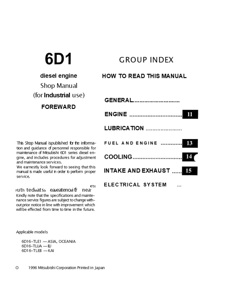
GROUP INDEX
diesel engine Shop Manual
HOW TO READ THIS MANUAL
(for Industrial use) FOREWARD
GENERAL.............................
ENGINE LUBRICATION ......................
FUEL AND ENGINE
This Shop Manual ispublished for the informa-
tion and guidance of personnel responsible for
maintenance of Mitsubishi 6D1 series diesel en-
gine, and includes procedures for adjustment and
maintenance services. We earnestly look forward
to seeing that this manual is made useful in
order to perform proper service.
INTAKE AND EXHAUST
ELECTRICAL SYSTEM ...
?St
Futh tedMatsb eadeatenodi tr nea Kindly note
that the specifications and mainte- nance service
figures are subject to change with- out prior
notice in line with improvement which will be
effected from time to time in the future.
Applicable models 6D16-TLE1 --- ASIA,
OCEANIA 6D16-TLUA --- EU 6D16-TLEB --- KAI
O
1996 Mitsubishi Corporation Printed in Japan
2
GROUP 00 GENERAL
00
GENERAL SPECIFICATIONS ...........................
.. ENGINE NUMBER AND NAME PLATE
............. PRECAUTIONS FOR MAINTENANCE
OPERATION ........... . . 4 TABLE OF STANDARD
TIGHTENING TORQUES ................ 12
00-1
3
GENERAL SPECIFICATIONS
Item Specifications Specifications Specifications Specifications Specifications Specifications
Engine model 6D14 6D14 T 6D15-T 6D16 6D16-T 6D16-TL
Type 6-cylinder in-line, water-cooled 4-cycle diesel 6-cylinder in-line, water-cooled 4-cycle diesel 6-cylinder in-line, water-cooled 4-cycle diesel 6-cylinder in-line, water-cooled 4-cycle diesel 6-cylinder in-line, water-cooled 4-cycle diesel 6-cylinder in-line, water-cooled 4-cycle diesel
Combustion chamber type Direct injection type Direct injection type Direct injection type Direct injection type Direct injection type Direct injection type
Valve mechanism Overhead valve (OHV) type Overhead valve (OHV) type Overhead valve (OHV) type Overhead valve (OHV) type Overhead valve (OHV) type Overhead valve (OHV) type
Bore x Stroke mm 110 x 115 110 x 115 113 x 115 118 x 115 118 x 115 118 x 115
Total displacement cc 6557 6557 6919 7545 7545 7545
Compression ratio 17.5 16 16 17.5 16 17.5
Empty mass kg" 500 540 540 500 550 580
Empty mass as measured according to Mitsubishi
Motors Corporation standard.
4
https//www.ebooklibonline.com Hello dear
friend! Thank you very much for reading. Enter
the link into your browser. The full manual is
available for immediate download. https//www.ebo
oklibonline.com
5
ENGINE NUMBER AND NAME PLATE ONO The serial
number lor engine is assigned to the respective
engine in manufacturing sequence every engine
has its own number. This number is required for
incidental inspection of the engine. Please do
not fail to mention this number to the dealers
when ordering spare parts. Engine Number Engine
number 1 is punch-marked on the left of the
crankcase. Example 6D16_at_Ed_at__at__at_EQ
Engine number
Engine model
Name Plate
The name plate is attached to the portion shown
in the illustration, and in- dicate the following
items.
18779
- Engine model
- Total displacement
- Maximum output
- Valve clearance
- Firing order
- Fuel injection timing
1
2
3
V4
18780
00-3
6
PRECAUTIONS FOR MAINTENANCE OPERATION
In order to determine the condition of the
vehicle adequately, attend the vehicle beforehand
to find and keep record of the accumulated
mileage, operating condition, what the customer's
demand is, and other information that may be
necessary. Prepare the steps to be taken and
perform efficient and wasteless maintenance
procedure. Determine where the fault exists and
check for the cause to see whether removal or
disassembly of the part is necessary. Then follow
the proce- dure specified by this manual.
- 387T0
- Perform maintenance work at a level area. Prepare
the following. - Prepare general and special tools necessary for
the maintenance work. - WARNING
- Do not attempt to use tools other than special
tools where use of special tools is specified in
this manual. This will avoid injury or damage.
- Pay special attention to safety when removing or
installing heavy items such as engines,
transmissions. - When lifting up heavy items using cables, pay
special attention to the fol- lowing points - Check the mass of the item to belifted and use a
cable capable of lifting that mass.
- If you do not have the specified lifting hanger,
sëcure the item using cable taking the
point-of-balance of the item into consideration.
14195
- You must work in a position where you will not
be injured even if the cable comes undone and the
lifted item falls.
00-4
7
Be particularly careful not to work in shoes that
have oily soles and are slippery. When working as
a team of two or more, arrange signals in ad-
vance and keep confirming safety. Be careful not
to accidentally bump switches or levers.
00012 Check for oil leakage before cleaning the
area having the fault otherwise you might miss
detecting the leakage. Prepare replacement
part(s) beforehand.
Replace oil seals, packing. O-rings and other
rubberpaRs gaskets and split pins with new parts
whenever any of them has been removed. Use only
genuine MITSUBISHI replacement parts.
00015
On disassembly, visually inspect all parts for
wear and tear, cracks, dam- age, deformation,
degradation, rust, corrosion, smoothness in
rotation, fatigue, clogging and any other
possible defect.
00016
00-5
8
PRECAUTIONS FOR MAINTENANCE OPERATION
Put alignment marks on part combinations before
disassembly and ar- range the disassembled parts
neatly. This will help avoid mismating of the
parts later. Put the alignment marks, punch
marks, etc. where performance and ap- pearance
will not be affected. Cover the area left open
after removal of parts to keep it free from
dust. CAUTION
- Take care to avoid mixing up numerous parts,
similar parts, left - and right, etc.
- Keep new parts for replacement and original
(removed) parts sep- arate.
00017
Apply the specified oil or grease to U-packings,
oil seals, dust seals and bearings during
assembly. Use only the specitied oil, grease,
etc. for lubricant, remove the excess immediately
after application with a piece of waste,
etc. CAUTION When the specified lubricant, fluid
and sealant is not available, you may use an
equivalent.
Wear goggles when using a grinder or welder. Pay
lull attention to safety by wearing gloves when
necessary. Watch out for sharp edges, etc. that
might injure your hands or fingers.
00019 Before carrying out maintenance work on the
electric system, disconnect the negative
terminals of the batteries to prevent them from
short-circuit- ing and burning-out. CAUTIONS Be
sure to turn starter and lighting switches, etc.
off before dis- connecting or connecting battery
terminals, because the semi- conductors can be
damaged.
016
9
Take care when handling sensors, relays, etc.
which are vulnerable to shock and heat. Do nol
attempt to remove the cover from, or apply paint
to, the electronic control unit.
00021 Pull the connector, and not the harness
lead, to separate connectors. To separate a
lock-type connector, first push toward arrow
mark. To recon- nect a lock-type connector, press
the separated parts until they click to- gether.
00022 When washing the vehicle, cover the
electric system parts and instru- ments with
waterproof material belorehand (Cover with vinyl
sheet or the like). Keep water away from harness
wire connectors and sensors. If any of them
should get wet, wipe them off immediately.
- When using an electric welder, such electronic
parts that are directly con- nected lo the
batteries might be damaged due to the flow of
current from the welder that flows through the
negative circuit. Parts that have switches might
be subject to the same danger if the switches are
left on. - Therefore, do not lail to observe the following.
- Connect the negative terminal of the welder as
near as possible to the area that is to be
welded. - Disconnect the negative terminals of batteries.
To apply voltage for testing, check thai the
positive and negative cables are connected
properly, then increase voltage gradually from 0
volt. Do not apply voltage higher than the
specified value. In particular, pay close
attention to the electronic control unit and
sensors, since they are not always fed the
battery volta9e.
00-7
10
PRECAUTIONS FOR MAINTENANCE OPERATION
When using testers or the like for continuity
tests, be careful not to allow test probes to
touch the wrong terminals.
00027 Measurement Procedures Using Connectors
Test with connectors engaged (continuity through
circuit obtained) ltWaterproof connectors Prepare
a test harness and connectors A, then connect if
between the two parts of harness B that is to be
tested. Check the circuit by touching test probe
C to the test connector. Never insert the test
probe from the harness side of the waterproof
con- nection, or waterproof performance might be
diminished causing corro- sion of the connector.
r " Connect the test harness and connector
A betwee these parts 02S87
ltNon-waterproof connectorgt Insert test probe C
from the harness side of the connector. Where
control units, etc. have connectors that are too
small to accept the test probe, do nol force the
test probe into them.
02588 Test with connectors disengaged Using
female pins Insert a test probe into a terminal.
However, do not force the probe into the
terminal, or it will cause a poor contact.
00-8
11
Using male pins Touch the pins directly using
test probes. CAUTION Be sure that you do not
short circuit the connector pins when you use the
test probe because this could damage the internal
circuit of the electronic control unit.
02590
Connector Inspection Procedures Visual
inspection Check for loose connection and poor
engagement.
Check if harnesses are broken by pulling gently
around the terminals.
02592 Check for a decrease in contact pressure
between the male and female terminals.
02593 Check for poor contact caused by connector
pins having fallen out, rusted terminals or
foreign particles.
00-9
12
PRECAUTIONS FOR MAINTENANCE OPERATION
Connector pin fall out inspection Damaged
connector pin stoppers can cause poor engagement
of the ter- minals (male and female pins) even if
the connector body is secured, and might cause
some pins to fall out. Check if the pins have
fallen out mom the connector by pulling each
harness gently.
- 02594
- Inspection Procedures for Blown Fuses
- Remove fuse B and measure resistance between the
loaded side of the fuse and ground. - Turn on all circuit switches (connected to lhe
fuse). If the resistance value - reading is approximately 0, a short has occurred
between the switch and the loaded point. A value
of other than zero may indicate that the fuse was
blown by a temporary short but the short is no
longer present. - The major causes of a short circuit are as
follows - Harness stuck onto the vehicle body.
- Harness sheath damaged by friction or heat.
- Water in connectors or circuits.
- Mistakes (accidental short circuits)
- A Battery B Fuse
- C Loaded swilch D Load
- E Short circuit
- Precautions for Handling Alternator
- When servicing the alternator, pay attention to
the following - Do not connect the alternator with battery
polarities reversed. - If the alternator is connected with reversed
polarities, a large current - flow from the battery to the alternator occurs,
and lhe diode or regulator might be damaged.
00-10
13
- While the engine is running, do not remove the
battery terminals. If the battery terminals are
removed at that time, a surge voltage is gener-
ated and the diode or regulator might be weakened.
- Do not use a high-voltage tester such as a
megger for inspection. If a high-voltage tester
is used, the diode or regulator might be
destroyed.
- Do not splash water over the alternator.
- If water is directly splashed over the
alternator, individual components will be
short-circuited and might be destroyed.
05165
- Do not short-circuit terminal B and terminal L
while running the alterna- tor. - If the terminals are short-circuited while the
alternator is running. the diode trio might be
destroyed.
- Disconnect the battery terminals before
quick-charging the battery. Quick-charging
without disconnecting the battery terminals might
damage the diode or regulator.
14
TABLE OF STANDARD TIGHTENING TORQUES
- Use specified bolts and nuts and tighten them at
specified torques according to the following
table, unless otherwise spe- cified. - Threads and contact seats shall be dry.
- Where there is a difference in strength
classification between the nut and bolt (or stud
bolt), the torque specified for the bolt shall
apply.
Hex-head Bolt and Stud Bolt
Unit N m kgf m)
Strength classification 4T 4T 8T 8T
Repre- sentation Diameter symbol (Stud) (Slud) (Stud) Oe 02154
M5 2 to 3 (0.2 to 0.3) 4 to 6 (0.4 to 0.6) 5 to 7 (0.5 to 0.7)
M6 4 to 6 (0.4 to 0.6) 7 to 11 0.7 to 1.1) 8 to 12 (0.8 to 1.2)
M8 9 to 14 (0.9 to 1.4) 17 to 26 (1.7 to 2.6) 20 to 29 (2.0 to 3.0
M10 19 to 28 (1.9 to 2.8) 18 to 26 (1.8 to 2.7) 36 tO 52 (3.5 IO '.5) 33 to 49 (3.5 to 5.0 45 to 60 (4.5 to 6.0) 41 to 59 4.3 to 6.9)
M12 35 to 50 (3.4 to 5.0) 3J to 46 (3.1 to 4.7) 70 to 95 (7.0 to 9.5) 65 io 85 (6.5 to 8.5) 85 to 110 (8.5 to 11) 75 to 100 (7.5 to 10)
M14 60 to 85 (6.0 to 8.5) 55 to 75 (5.5 to 7.5) 120 to 160 (12 to 16) 110 lo 140 (11 to 14) 130 \o 180 (13 Io 1B) 120 to 160 (12 to 17
M16 90 to 130 (9.5 to 13) 90 to 120 (9.0 to 12) 180 to 240 (18 to 24) 160 to 220 (16 to 22) 200io270 (20to27) 190 to 260 (19 to 26)
I\418 140 to 190 (14 to 19) 120 to 160 (12 to 16) 260 to 340 (25 to 35) 220to290 22to301 290 to 390 (30 to 40) 260 to 340 ( 26 to 35)
M20 190 to 260 (19 to 26) 170 to 230 (17 to 23) 350 to 470 (36 to 48) 320to420 (32 to 43) 410 to 550 (41 to 56) 370 to 490 (37 to 50)
M22 260 to 340 (26 to 35) 230 to 300 (23 to 31) 470 to 640 (48 to 65) 430to570 (43 to 58) 550 to 740 (56 lo 75) 490 to 670 (50 to 68)
M24 340 to 450 (34 to 46) 290!o390 29to4O) 630 to 840 (63 to 86) 540 to 730 (55 to 74) 730 to 980 (74 to 100) 630 to 840 (64 to 86)
Hex-head Flange Bolt
Unit N-m (kgf -m
Strength classification 4T 4T BT BT
Repre- sentation Diameter symbol _at_
M6 4 to 6 (0.4 to 0.6) 8 to 12 0.8 lo 1.2) 9 to 14 (0.9 to 1.4)
M8 10 to 15 (1.0 to 1.5) 19 to 28 (1.9 to 2.8) 22 to 32 (2.2 to 3.3)
M10 21 to 30 (2.1 to 3.1) 20 to 28 (1.9 to 2.9) 39 to 58 (3.9 to 6.0) 37 to 53 (3.6 to 5.4) 50 to 65 (5.0 to 6.5) 45 to 65 (4.5 to 6.5)
MA2 38 to 54 (3.8 Io 5.5) 35to51 (3.4to5.2) 80 to 110 (8.0 to 11 70 to 95 (7.0 to 9.5) 90 to 120 (9.0 to 12) 85 to 110 (8.5 to 11)
00- J2
15
Hex-head Nut
Unit N -m ( kgf m)
Strength classification 4T 4T 6T 6T
Repre- sentation Diameter symbol 024 55 024 55
Repre- sentation Diameter symbol Standard screw Goarse screw Standard screw Coarse screw
M5 2 to 3 (0.2 to 0.3) 4 to 6 (0.4 to 0.6)
Il6 4 to 6 (0.4 to 0.6) 7 to 11 (0.7 to 1.1)
M8 9to14 0.9to1.4) 17 to 26 (1.7 to 2.6)
M10 19 to 28 (1.9 to 2.8) 18 to 26 (1.8 to 2.7) 36 to S2 (3.5 to 5.5) 33 to 49 (3.5 to 5.0)
M12 35 to 50 (3.4 to 5.0) 31 to 46 (3.1 to 4.7) 70to95 7.0o9.5) 65 to 85 (6.5 to 8.5)
M14 60 to 85 6.0 to 8.5 55 to 75 (5.5 to 7.5) 120 to J60 (12 to 16) 110 to 140 (J1 to 14
M16 90 to 130 (9.5 to 13) 90 to 120 (9.0 to 12) 180 to 240 (18 to 24) 160 to 220 (16 lo 22)
M18 140 to 190 14 to 19) 120 to 160 (12 to 16) 260 to 340 (25 to 3S) 220 to 290 (22 to 30)
M20 490to260 (19 to 26) 170 to 230 (17 to 23) 350 to 470 (36 to 48) 320 to 420 (32 to 43)
M22 260 to 340 26 io 35 230 io 300 (23 to 31) 470 to 640 (48 to 65) 430 to 570 (43 to 58)
M24 340 to 450 34 to 46) 290 to 390 (29 to 40) 630 to 840 (63 to 86) 540 to 730 (55 to 74)
Hex-head Flange Nut
Unit N-m kgf -m)
Strength classification 4T 4T
Repre- sentation Diameter symbol 02155 02155
Repre- sentation Diameter symbol Standard screw Coarse screw
M6 4 to 6 0.4 to 0.6)
M8 10 to 15 (1.0 to 1.5)
M10 21 to 30 (2.1 to 3.1) 20 la 28 (1.9 to 2.9)
M12 38 to 54 (3.8 to 5.5) 35 to 51 (3.4 to 5.2)
16
TABLE OF STANDARD TIGHTENING TORQUES
Tightening torque for flare nut for general
purpose
Unit N -m kgf -m)
Pipe diameter 4.76 mm 6.35 mm 8 mm Q10 mm 12 mm 15 mm
Tightening lorque 17 (J.7) 25 (2.6) 39 (4.0 59 (6.0) 88 (9.0) 98 (10.0)
Tightening torque for air piping nylon tube for
general purpose DIN type
Unit N- m (kgf m)
Standard diameter 6 x 1 mm 10 x 1.25 mm 12 x 1.5 mm 15 x 1.5 mm
Tightening torque 2 5.9 2.0 0.6 t 5.0 1.0 544.9 5.5 1.0
Tightening torque for air piping nylon tube for
general purpose SAE type
Unit N -m (kg-f m)
Standard diameter 1/4 in. 3/8 in. 1/2 in. 5/8 in.
Tightening torque 1 g 1.3 0.4 29_ .9 t 3.0 0.5 494.9 ( 5.0 0.5 644.9 ( 6.5 0.5
00-14
17
11
- ltM10 Boltsgt
- After filing the M14 cylinder head bolts 8,
tighten the M10 bolts to the spencified torque
(34 N-m (3.5 kgf -m)) in the sequence shown.
O O O
O O O O O O O O
O O O
01945 11 Cylinder head gasket Remova
l CAUTION When removing the cylinder head gasket
11, be careful not to scratch the cylinder head
and valve assembly 10 and the crank- case .
- FittingJ
- Fit the cylinder head gasket 11 onto the
crankcase as shown.
13582
12 Push rod runout If any measurement exceeds the
specified limit, replace the defective part(s).
12
01948
Tappet-to-crankcase clearance If any measurement
exceeds the specified limit, replace the
defective part(s).
13
1949
II -l5
18
Suggest For more complete manuals. Please go to
the home page. https//www.ebooklibonline.com If
the above button click is invalid. Please
download this document first, and then click the
above link to download the complete manual. Thank
you so much for reading
19
CYLINDER HEAD AND VALVE MECHANISM Rocker and
Bracket Assembly
- Disassembly sequence
- Rocker assembly
- Rocker bushing
- Lock nut
- Adjusting screw
- Rocker
- No. 6 rocker shaft bracket
- Set screw
- No. 5 rocker shaft bracket
- No. 4 rocker shaft bracket
- No. 3 rocker shaft bracket
- No. 2 rocker shaft bracket
- No. 1 rocker shaft bracket
- Rocker shaft spring
- Rocker shaft
- G Assembly sequence
- Reverse the order of disassembly.
Service standards
Unit mn
Standard value (Basic diameter in ( ) 24) 0.01
to 0.08
Location
Maintenance item
Limit
Remedy
2, 14
Rocker bushing-to-rocker shaft clearance
0.12 Replace Unit N m (kgf m Remarks
0 Tightening torques
Location 3 7
Parts to be tightened Adjusting screw lock nut
Rocker shaft set screw
Tightening torque 34 (3.5) 3.9 (0.4)
_at_ Oils Location 2
Points of application Rocker bushing inner surlace
Quantity As required
Kinds
Engine oil
_at_ Special tools Location
Unit mr
Tool name and shape
Part No.
Application
26
24
Rocker Bushing Puller
MH061777
Removing and installing rocker bushings
01951
II- Id
20
11
4 Service procedure 2 Rocker bushing and rocker
shaft lnspectionJ If any clearance exceeds the
specified limit, replace the defective part(s).
01952 Rocker bushing Removal)
- Installation)
- Align the oil hole A in the rocker bushing 2
with the oil hole B in the rock- er 5. - Position the notch C and seam D on the rocker
bushing 2 as shown. - Install the rocker bushing 2 into the rocker 5
lrom the chambered side F.
12995
to12 lnstalling rocker shaft brackets and
rocker shaft Rocker shaft brackets Be sure to fit
the rocker shaft brackets 6, 8, 12 in their
correct positions.
9, 10, 12 B 13023
A Oil hole B Threaded hole (for M8 rocker cover
bolt) C Threaded hole (for M6 set screw) D No
threaded hole
II -17
21
https//www.ebooklibonline.com Hello dear
friend! Thank you very much for reading. Enter
the link into your browser. The full manual is
available for immediate download. https//www.ebo
oklibonline.com
Recommended
