
CASE 1700 UNI-LOADER Service Repair Manual Instant Download (Book Code No. 9-72096R0) PowerPoint PPT Presentation
Title: CASE 1700 UNI-LOADER Service Repair Manual Instant Download (Book Code No. 9-72096R0)
1
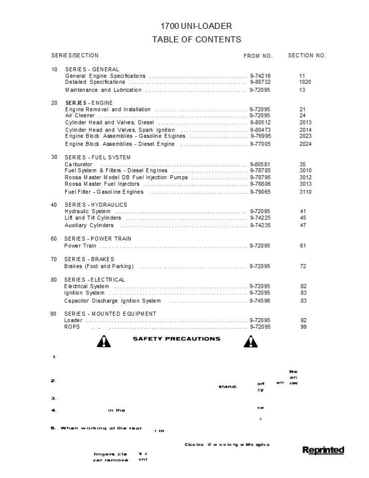
1700 UNI-LOADER TABLE OF CONTENTS
SERIES/SECTION
FROM NO.
SECTION NO.
10 SERIES - GENERAL General Engine Specifications ................................... 9-74216 11
Detailed Specifications .......................................... 9-80732 1020
Maintenance and Lubrication .................................... 9-72095 13
20 SER.IES - ENGINE Eng ine Removal and Installation ................................. 9-72095 21
Air Cleaner ..................................................... 9-72095 24
Cylinder Head and Valves, Diesel ................................ 9-80512 2013
Cylinder Head and Valves, Spark Ignition ........................ 9-80473 2014
Eng ine Block Assemblies - Gasoline Etgines ..................... 9-76995 2023
Eng ine Block Assemblies - Diesel Engine ........................ 9-77005 2024
30 SERIES - FUEL SYSTEM
Ca rburetor .................................................... 9-80581 35
Fuel System Filters - Diesel Eng ines ........................... 9-78785 3010
Roosa Master Model DB Fuel Injection Pumps .................... 9-78795 3012
Roosa Master Fuel lnjectors ..................................... 9-78806 3013
Fuel Filter - G asol ine Engines ................................... 9-79065 3110
40 SERIES - HYDRAULICS Hydraulic System ............................................... 9-72095 41
Lift and Tilt Cylinders ........................................... 9-74225 45
Auxiliary Cylinders ............................................. 9-74235 47
60 SERIES - POWER TRAIN
Power Train .................................................... 9-72095 61
70 SERIES - BRAKES
Brakes (Foot and Parking) ...................................... 9-72095 72
80 SERIES - ELECTRICAL
Electrical System ............................................... 9-72095 82
Ignition System ................................................. 9-72095 83
Capacitor Discharge Ignition System ............................ 9-74596 83
90 SERIES - MOUNTED EQUIPMENT Loader ......................................................... 9-72095 92
ROPS . .. ................................................. 9-72095 99
C is a i no if w n n in ltg w itfz egr iv a
Reprinted
2
GENERAL ENGINE SPECIFICATIONS 1740 UNI-LOADER THE
MODEL AND ENGINE SERIAL NUMBER IS STAMPED ON A
PLATE LOCATED ON THE SIDE OF THE ENGINE ABOVE THE
CRANKING MOTOR.
D'ESEL ENGINES
General
Type ...........................................
Case Open Chamber, 4 Cylinder, 4 Stroke Cycle,
Valve In-Head Flring Order ......................
..................................................
................................................
1-3-4-2 Bore ....................................
..................................................
.................................. 3-13/16
Inches Stroke ....................................
..................................................
................................... 4-1/8
Inches Piston Displacement ......................
..................................................
................... 188 Cubic Inches Compression
Ratio ............................................
..................................................
............. 1T.5 to l to Load Governed S-pee-d
- --- -----.......................................
..................................... 2150
RPM Rated Engine Speed ..........................
..................................................
.......................... 2000 RP? I Engine
Idling Speed ....................................
..................................................
....... 950 to 1000 RPñt "Valve Tappet Clearance
(Exhaust) .......................................
............... (Hot and Cold .014 Inch i
Intake) .........................................
................ (Hot and Cold) .014 Inch "Hot
Settings Are blade After the Engine Has Operated
At Thermostat Controlled Temperature for At
Least Fifteen Minutes. Piston and Connecting
Rods Rings per Piston ...........................
..................................................
............................................ 3
Number of Compression Rings .... .........
........................... .. ............
......... . ............ .. .. . . 2 Number of
Oil Rings ., ...... . .... .. ... . ...... ..
................... ... ............... ....
..... . .... ........ . ... 1 Type Pins
..................................................
..................................................
.... Full Floating TJ pe Type Bearing
................................. Replaceable
Precision, Steel Back, Copper-Lead Alloy
Liners Main Bearings .Number off Bearings
..................................................
..................................................
................ 5 Type Bearings
................................ Replaceable
Precision Steel Back, Copper-Lead Alloy
Liners Engine Lubricating System Crankcase
Capacity ......... ............. .. .... .. ...
.. .. ....... .................... ... ... ...
.... ... .. . .. 4 Quarts With Filter Change
................. ............ . ..... .... .
......................... ... ..
................... 5 Quarts Oil Pressure
............. 50 to 70 Pounds z'ith Engine iVarm
and Operating at Rated Engine Speed Type System
..................................................
.............................. Pressure and Spray
Circulation Oil Pump ............................
..................................................
........................................ Gear
Type Oil Filter .................................
..................................................
.............. Full Flow Spin on Type Fuel
System Fuel Injection Pump ......................
..................................................
....................... Roosa-Master Pump
Timing . .... . ... . ..... . ............ .. ..
.. .. .......... ... ....... 2 Degrees Before Top
Dead Center Fuel Injectors i Prior to Eng. SN.
2734508 ..................... Pencil Type
fOpening Pressure 2500 PSI Fuel Injectors i
Starting z ith Engine SAN 2734'i09l ........
Penctl Type tOpening Pressure 3200 PSI Fuel
Transfer Pump ....................................
............ Vane Type, Integral Part of
Injection Pump Governor ............ Variable
Speed, Fly-Weight Centrifugal Type, Integral
Part of Injection Pump 1st Stage ruel Filter I
Prior to Eng. SN 2 i18490........................
.......... Replaceable Element Type 2nd Stage
Fuel filter ( Prior to Eng. S.N 2i184901
................................ Replaceable
Element Ti pe 1st Stage Fuel filter i Starting
with Eng. SAN 2?18490) .........................
.................... Spin on Type 2nd Stage Fuel
filter (Starting with Eng. SN 2715490)
.............................. .... ........ Spin
on W pe
Roc. 9-74216
CASE CORPORATION
3
GENERAL ENGINE SPECIFICATION 1737
UNI-LOADER SPARK IGNITION ENGINES
General Type .....................................
........................................ 4
Cylinder, 4 Stroke Cycle, Valve-in-Head
Ftring Order ...................................
..................................................
-.............................-... 1-3-4-2
more..............................................
..................................................
...........................3-3/8zne
Stroke ...........................................
..................................................
............................ 4.1/8
Inches Compression Ratio .........................
..................................................
.................................. /.1 IN
! Plston Displacement ...........................
.................................................-
-... .....- .. 148 Cubic Inches NoLoadGovernedSpee
d ...............................................
...............................................215
0RPM Rated Engine Speed ..........................
..................................................
.......................... 2000 RPM Engine Idling
Speed ............................................
................................................
950 to 1000 RPM Valve Tappet Clearance
(Intake ..........................................
............ (Hot and Cold) .014 Inches tExhaust)
................................
...................................(Hot) .014
Inches (Cold) .020 Inches Exhaust Ya1ve
Rotators ........................................
..................................................
. Positive Type Hot Settings Are Made After
The Engine Has Operated At Thermostat Controlled
Temperature For At Least Fifteen Minutes. Piston
and Connecting Rods Rings per Piston .........
.. . ........... ... .................. ..... ..
............ ......... ....... ....
................... .. .. 4 plumber of
Compression Rings ..............................
.............,....................................
.................... 3 Number of oi1 Rings .....
.. ..... . ..... ... ........ ...................
... .-.. ... ... . .... ....... ..... ....
.......... . 1 Type Pin ......................
..................................................
................................. Full Floating
Ty pe Type Bearings .............................
. Replaceable, Precision Steel Back, Copper Lead
Alloy Liners. Main Bearings Number of Bearings
.................................................
..................................................
................. 3 Type Bearings
............................... Replaceable,
Precision Steel Back, Copper Lead Alloy
Liners Engine Lubricating System Crankcase
Capacity .... . .. ..... .... . . .. . .. .. ..
. ..... ................. ...... .. .. ... . ....
.. .. 4 "yiarts Yt'ith Filter Change .........
... .... ... .. .. .. .... . .....
............... .... . ........... .. ..
.............. 5 Quarts Oil Pressure
............. 24 to 32 Pounds with Engine Warm
and Operating at Rated Engine Speed Type System
.................................................
...................................... Pressure
Spray Circulation 0i1 Pump ......................
..................................................
..............................................
Gear Type Oil Filter ...........................
..................................................
................... Full Flow, Spin on
Type Fuel System Carburetor ....................
..................................................
...................Marvel-Schebler TSX
Series Distributor Ignition Contact Point Gap
..................................................
..................................................
....... .020 Inch Dwell Angle
..................................................
..................................................
.......................... 42 Spark Plugs
..................................................
..................................................
........ Prestolite 18 8 Plug Gap
..................................................
..................................................
..................... .925 Inch Thread
.............. ... .. . .... ........
................. .......... ... .... .
............ ..... . . ...... ................
18 LtM Shank Length ... . ......... . . ......
... . ... ... ...... ............ .... ........
... .......... 1 2 Inch Engine Timing Static
Timiny .. ..... ....... .. . . ..............
.......... .. ... .... . ................ .. ...
. ..... ... .. G" BTDC Running Timing
..................................................
...................... 40 BTDC at Rated Engine-
Speed
4
https//www.ebooklibonline.com Hello dear
friend! Thank you very much for reading. Enter
the link into your browser. The full manual is
available for immediate download. https//www.ebo
oklibonline.com
5
Section
1020
DETAILED SPECIFICATIONS 480 AND 580 SERIES B
TRACTORS
TABLE OF CONTENTS ENGINE BLOCK ...............
... .......... . . . .. . . .... 2 CYLINDER HEAD
AND VALVES .......................................
..................................................
..... 7 COOLING SYSTEM ..........................
..................................................
....................................... 10 ENGINE
OIL FILTER ......................................
..................................................
...................... 11 AIR CLEANER
................................... ..............
.............. ...............................
. . .... 11 FUEL SYSTEM ..........................
..................................................
.............................................
12 BRAKES .......................................
..................................................
...........................................
14 POWER TRAIN ..................................
..................................................
..................................... 15 STEERING
.................................................
..................................................
............................. 16 GENERAL TORQUE
TABLE ...........................................
... .... ......................... . . .......
17 SPECIAL TORQUES .......... ................ .
... ....................... .. .. ..........
.............. .. . .............. l7
Rae. 9-80732
PRINTED IN U S A
CASE CORPORATION
6
1020-2 Engine Block NOTE All dimensions are
given in inches. Specifications apply to all
engines unless noted. Maximum Limit Including
Wear
CYLINDER SLEEVES
I.D. of sleeve (159G) ............................................... 3.5013 to 3.5028 ................................ .005
(188D) ............................................... 3.8115 to 3.8125 ................................ .005
(188G) ............................................... 3.8130 to 3.8145 ................................ .005
(148G) ............................................... 3.3745 to 3.3765 ................................ .005
Sleeve out-of-round .............................
..................................................
................................ .004 Clearance
to bottom of piston skirt (188D)
................ .0035 to .0055
(188G) (159G) (148G)
..................................................
.0025 to .0055 ..................................
................ .0015 to .0045 ..................
................................ .001 to .003
Taper ...........................................
..................................................
...................................... .001
PISTON Type .....................................
...................................... Cam
Ground Material .................................
............................... Aluminum
Alloy O.D. at bottom of skirt 900 to piston pin
(188G) .... 3.8090 to 3.8105
(188D) .......,....................................... 3.8070 to 3.8080 .......,....................................... 3.8070 to 3.8080 .......,....................................... 3.8070 to 3.8080
(159G) ............................................... 3.4983 to 3.4998 ............................................... 3.4983 to 3.4998 ............................................... 3.4983 to 3.4998
(148G) ............................................... 3.373 to 3.3T50 ............................................... 3.373 to 3.3T50 ............................................... 3.373 to 3.3T50
I.D. of piston pin bore (188D) ................................. 1.2500 to 1.2503 I.D. of piston pin bore (188D) ................................. 1.2500 to 1.2503 ............................... .001
(188G, 159G) ......................................... .9992 to .9994 (188G, 159G) ......................................... .9992 to .9994 ............................... .001
(148G) .................................................. .8592 to .8594 (148G) .................................................. .8592 to .8594 ............................... .001
Width of 1st ring groove (188D)
.............................. Keystone
Type (188G, 159G, 148G) ..........................
..... .0965 to .09T5 Width of 2nd ring groove
(188D) ................................... .097
to .098 (148G, 159G, 188G) .......................
........ .0955 to .0965 Width of 3rd ring groove
(18ßD) ................................ .1885 to
.1895 (188G, 159G, 148G) .........................
...... .0955 to .0965 Width of 4th ring groove
(188G, 159G, 148B) ................. .250 to .251
PISTON RINGS No. 1 Compression (188D)
..................... Chrome Grooved
Keystone (188G, 159, 148G) ..................
Chrome Tapered Face Width (188D)
..................................................
.... Not Measureable (188G, 159G, 148G)
............................... .0930 to .0935
7
1020-3
Engine Block (Continued)
Maximum Limit Including Wear
PISTON RINGS (Continued) End gap (188D)
............................. ....................
....... .015 to .025
(148G, 159G, l88G) ......................
........................... .010 to .020 Side
clearance (188D) .................................
...... Not Measureable (188G, 159G, 148G)
...............................................
.0030 to .0045 No. 2 Compression (188G, 159G,
148G) ..................... Tapered Face Width
(188G, 159G, 148G) ...............................
........ .0930 to .0935 (188D) ...................
..............................................
.0925 to .0935 End gap (188D) ....................
..................................... .015 to
.025 (148G, 159G, 188G) ..........................
........................ .010 to .020 Side
clearance (188D) .................................
............ .0035 to .0055 (188G, 159G, 148G)
...............................................
.0020 to .0035 No. 3 Compression (188G,159G,148G)
........................ Tapered face Width
..................................................
................. .0930 to .0935 End gap in 3.812
sleeve (188G, 159G, 148G) ................. .010
to .020 Side clearance .. .......................
............................... .0020 to
.0035 OIL RINGS
Width (188D)
......... ........................................
... .1825 to .1888
(188G,159G,148G) .................................
. .2485 to .2490 Side clearance (188D)
..................................................
.. .000 to .007 (188G,159G,148G)
.................................. .0010 to
.0015 End gap (188G, l59G, l48G) .................
........................ .010 to .018 Rail end
gap (188D) ...........................
........................... .015 to .055
8
1020-4
Engine Block (Continued)
Maximum Limit Including Wear
PISTON PIN Type ..................................
......................................... Full
Floating O.D. of pin (188D) ......................
............................. 1.2497 to
1.2498 (188G, 159G) ..............................
........... .9991 to .9992 (148G)
..................................................
.8592 to .8593 Fit in piston (188D)
..................................................
.. .0002 to .0006 (188G, 159G) ...................
...................... .0000 to .0003 (148G)
..................................................
.0ooo to .0o02 Fit in rod bushing (188D)
........................................... .0002
to .0006 (188G,159G,148G) ........................
.......... .0003 to .0006 CONNECTING ROD Bushing
..................................................
.......... Replaceable Bronze Bushing I.D.
installed (reamed to size) (188G,159G)
.......................................... .9995
to .999T (188D) ..................................
............. 1.2502 to 1.2504 (148G)
..................................................
.8596 to .8598
................................
.002 ................................
.002 ................................ .002
Bushing out-of-round ...... ......................
..................................................
............................. .0015 Bearing
Liners ..........................................
................... Replaceable Bearing liner
width ...........................................
......... 1.120 to 1.130 Rod width at crank end
.......................................... 1.3035
to 1.3055 Journal I.D. without bearing liners
......................... 2.1870 to 2.1875
Bearing oil clearance ...........................
...................... .0010 to .0035 Undersize
bearings for service .............................
. .002,.010,.020,.030 Side clearance
..................................................
............. .005 to .011 Cap bolts
..................................................
............ Self locking type CRANKSHAFT Type
..................................................
............................... Balanced Main
bearing liners ..................................
................... Replaceable
................................ .006
End play, center main bearing cap .... ... ....
. ............. .001 to .006 .....................
............... .012 Center main bearing thrust
surface thickness ...............................
........................ .1025 to
.1045 Connecting rod journal std. O.D.
............................. 2.0605 to
2.0615 Grind to .010 O.D. undersize ............
..................... 2.0505 to 2.0515 .020 O.D.
undersize .......................... 2.0405 to
2.0415 .030 O.D. undersize ......................
.... 2.0305 to 2.0315
9
1020-5
Engine Block (Continued)
Maximum Limit Including Wear
CRANKSHAFT (Continued) Journals out-of-round
..................................................
.............. .001 Main bearing liner width 1st,
(188D, 188G) ................ 1.276 to 1.286 Main
bearing liner width 1st, (159G, 148G)
................ 1.870 to 1.880 Main bearing
liner width 3rd (188D) ..........................
1.371 to 1.373 Main bearing liner width 2nd
(188G) ......................... 1.371 to 1.373
Main bearing liner width 2nd and 4th (188D)
.............. .950 to 1.000 Main bearing liner
width 5th (188D), (188G 3rd.) ...... 1.557 to
1.567 Undersize main bearing liners for service
............ .002,.010,.020,.030 Main bearing oil
clearance ........................................
. .0012 to .0042 Main bearing journal std. O.D.
(188G, 188D) .......... 2.8730 to 2.8740
(159G,148G) ......................................
. 2.6230 to 2.6240 Grind to
.010 O.D. undersize, (188G, 188D) .020 O.D.
undersize, (188G, 188D) .030 O.D. undersize,
(188G, 188D) .010 O.D. undersize, (l59G,
148G) .020 O.D. undersize, (159G, 148G) .030
O.D. undersize, (159G, 148G)
....................... 2.8630 to
2.8640 ....................... 2.8530 to
2.8540 ....................... 2.8430 to
2.8440 ....................... 2.6130 to
2.6140 ....................... 2.6030 to
2.ñ040 ....................... 2.5930 to 2.5940
Main journal bore I.D. w/o liners (188D, 188G)
......... 3.066 to 3.067 (159G,148G)
.......................................... 2.816
to 2.817 Main journal width between cheeks 2nd
(159G, 148G) ....................................
................. 1.499 to 1.502 2nd and 4th
(188D) .......................................
........... 1.185 to 1.189 2nd (188G)
..................................................
.......... 1.3770 to 1.3740 3rd (188D)
..................................................
.......... 1.3740 to 1.3770 3rd (159G, 148G,
188G) ............................................
1.745 to 1.755 5th (188D) .......................
......................................... 1.745
to 1.755 Connecting rod journal width between
cheeks ........... 1.3105 to 1.3145 CAMSHAFT Type
.................................................
...............................
Parabolic Bushings (188D) ........................
............................... 5,
Replaceable Bushings (188G) ......................
................................. 4,
Replaceable Bushings (159G, 148G)
............................................. 3,
Replaceable Oil Clearance ........................
......................................... .002 to
.005.................................... .007
10
1020-6
Engine Block (Continued)
Maximum Limit Including Wear
CAMSHAFT (Continued) Bushing lubrication Front
bushing .........................................
...... Pressure lubricated from oil pump.
Intermediate bushing ............................
..... Gravity flow lubricated Rear bushing (188D
Only) ....................... Pressure
lubricated with rear oil metering. I.D. of
bushing installed ................................
............. 1.752 to .1753 Bushing width 1st
(front) (159G,148G) ..............................
.............. 1.307 to 1.317 1st (front) (188D,
188G) ............................................
1.213 to 1.223 2nd (159G,148G) ..............
........ ................................... .713
to .723 2nd, 3rd 4th (188D) ....................
............................. .490 to .500 2nd,
3rd. (188G) ......................................
................ .490 to .500 3rd (rear) (148G,
159G) ...........................................
1.177 to 1.197 4th (rear) (188G)
..................................................
... 1.213 to 1.223 5th (rear) (188D)
..................................................
... 1.213 to 1.223 O.D. of each bearing siytace
................................... 1.749 to
1.750 Thrust plate thickness ....................
............................ .149 to
.147 Camshaft end play ..........................
..... Taken up by thrust plate Camshaft end
clearance .......................................
...... .003 to .007 VALVE PUSH ROD LITTERS Type
..................................................
............................. Mushroom Body O.D.
std. .............................................
............... .5605 to .5610 I.D. of block
bore, std. .......................................
........ .5625 to .5635 GEAR TRAIN Backlash Crank
shaft gear to camshaft gear .....................
.......... .0002 to .006 Camshaft gear to idler
gear (Diesel) .......................... .0004
to .006 Idler gear to fuel pump gear (Diesel)
......................... .0005 to
.007 Crankshaft gear to oil pump gear
................................. .002 to .008
.............................. .004
.............................. .0015
11
1020-7
Engine Block (Continued)
Maximum Limit Including Wear
IDLER GEAR O.D. of idler gear journal (Diesel)
......................... 1.3740 to 1.3755 I.D.
of idler gear w/bushing (Diesel)
......................... 1.376 to 1.377 Thrust
washer shims (Diesel) ...........................
.... .005,.006,.007,.009
............................... .0005
Idler gear end play (Diesel) ...................
..................................................
........................... .003 OIL PUMP FRONT
MOUNTED Positive displacement pump
.......................................... Gear
Type Pump gears to oil pump cover clearance
.................. .0015 to .0055 Pump gears
radial clearance ................................
........ .002 to .005 Drive gear to body
clearance (l88G,l59G,l48G) ............ .003 to
.006 Drive gear to body clearance (188D)
......................... .0035 to .0065 Relief
valve spring Wire thickness (188D)
..................................................
........... .0625 Maximum O.D. (188G,l59G,148G)
..............................................
.469 Maximum O.D. (188D) ........................
.................................... .4844 Free
length (188G,159G,148G) .........................
.............................. 2 Free length
(188D) ..........................................
........................ 2-1/8 Load at 1.38
inches (188G,159G,148G) .................. 6-3/4
to 7-1/4 lbs. Load at 1.44 inches (188D)
.......................................... 18 to
19 lbs. Oil pressure (188G,159G,148G)
..................................... 24 to 32
PSI Oil pressure (188DQ .........................
............................ 50 to 70
PSI Backlash, crankshaft drive gear and oil pump
gear ........ .002 to .008 Cylinder Head and
Valves Diesel Engines
CYLINDER HEAD Warpage
....... ..........................................
..
. .................. ..............., .0 "
EXHAUST VALVES Tappet Clearance (Hot and Cold)
............. Face Angle
. ..........
.014" . Who
....... ................... .
Face Run-Out ....................................
.......
.002
O.D. of Head ...... O.D. of Stem .......... ...
. ' h
............ .... ....
. 1.398 to 1.408
.3399 to .3409............. .002
. 6.340 to 6.364
Lnner t Seat Angle
Seat Face Width ".." "" "."
.0608 to .0962
Seat Run-Out ....................................
........ .............................
.002
12
1020-8
Cylinder Head and Valves (Continued) EXHAUST
VALVES (Continued)
Maximum Limit Including Wear
Insert Height ...................................
..............................................
.2475 to .2525 O.D. of Insert .
..................................................
.......................... 1.4450 to
1.4505 I.D. of Insert ..........................
..................................................
..... 1.245 to 1.255 INTAKE VALVES Tappet
Clearance (Hot and Cold) ......................
............................................
.014 Tj e Anglp . ....... ....................
. . . ............................................
..................... 44 Face Run-Out
..................................................
..................................................
................. .002 O.D. of Head
..................................................
............................... 1.599" to
1.609" O.D. of Stem .............................
..................................................
.. .3409" to .3419" ............. .002" Length
..................................................
......................................... 6.339"
to 6.364"
Seat Angle .............. .... ................
..................................................
............. 45o
sent Run-out .. . . ... ... . ........ ... . .
..................................... ...
...................................... . 2- Seat
Width ............................................
...................................... .0704 to
.1057
EXHAUST VALVE GUIDES Length .....................
..................................................
................................... 3.125 O.D.
..................................................
.............................................
.6565 to .6575 I.D. (Installed and Reamed)
..................................................
....... .3429 to .3439............. .001 Valve
Stem Clearance in Guide ..........................
.............................. .002 to
.004 Protrusion Above Cylinder Head
..................................................
................. .875 INTAKE VALVE
GUIDES Length ...................................
..................................................
..................... 3.250 O.D.
..................................................
.............................................
.6565 to .6575 I.D. (Installed and Reamed)
..................................................
....... .3429 to .3439............. .001 Valve
Stein Clearance in Guide .........................
............................... .001 to
.003 Protrusion Above Cylinder Head
..................................................
................. .875 VALVE SPRING Free Length
..................................................
...............................................
2.375 Total Coils .............................
..................................................
........................ 8.25 Wire Diameter
..................................................
.............................................
.162 I.D. .......................................
..................................................
.......... .958 to .978 Compressed to 1.521
(Valve Open) ....................................
............ 110 to 118 lbs. Compressed to 1.875
(Valve Closed) ..................................
............... 53 to 59 lbs. ROCKER ARM
ASSEMBLY O.D. of Shaft ..........................
..................................................
........ .622 to .623 I.D. of Arm Bore
..................................................
............................ .624 to .625 Shaft
Spring Free Length . .......................
. . . . ... ..... .. . . . . ..... .
2.5 Wire Diameter ..............................
..................................................
............ .072 Compressed to 1.75 ......
... . . ...... ........ . . .... . . 7.5
to 8.5 lbs. Lubrication .........................
................................... Engine oil,
camshaft metering Shaft Oil Holes
..................................................
...... Toward valve side of engine, shaft cannot
be rotated.
13
1020-9
Cylinder Head and Valves (Continued) Spark
Ignition Engines Maximum Limit Including
Wear CYLINDER HEAD Warpage ......................
..................................................
..................................................
.006" SPARK PLUG Gap Setting (18mm)
..................................................
....................................
.025 EXHAUST VALVE Tappet Clearance (COLD)
..................................................
........................... .020 (HOT)
..................................................
................................ .014 Face Angle
.................................................
..................................................
.... 44 Face Run-out ............................
..................................................
........................................
.002 Length (188 and 201) ......................
...............................................
5.824 to 5.844 Length (148 and 159)
..................................................
................... 5.309 to 5.334 O.D. of Head
(188 and 201) ..................................
......................... 1.398 to 1.408 O.D.
of Head (148 and 159) ..........................
................................. 1.265 to
1.275 O.D. of Stem .............................
..................................................
.. .3382 to .3390............. .002 Insert
Seat Angle .......................................
..................................................
..... 450 Seat Contact Width (188 and 201)
..................................................
... .072 to .085 Seat Contact Width (148 and
159) .............................................
........ .090 to .100 Seat Run-Out
..................................................
..................................................
.................. .002" Insert Height (188 and
201) ............................................
............... .2475 to .2525 Insert Height
(148 and 159) ...........................
.................. .............. .198 to
.203 O.D. of Insert (188 and 201)
..................................................
..... 1.4495 to 1.4505 O.D. of Insert (148 and
159) .............................................
.......... 1.3765 to 1.3775 I.D. of Insert (188
and 201) .........................................
.................. 1.245 to 1.255 I.D. of
Insert (148 and 159) ............................
............................... 1.074 to
1.084 INTAKE VALVE Tappet Clearance (HOT AND
COLD) ...........................................
................. .014 Face Angle
..................................................
..................................................
... 29 face Run-Out ........ ...
..................................................
...... ... ..... . ............. ............
....... Length (18b and 201) ....................
.................................................
5.796 to 5.816 Length (148 and 159)
..................................................
................... 5.275 to 5.300 O.D. of Stem
.................................................
................................ .3406 to
.3414 O.D. of Head (188 and 201)
..................................................
......... 1.514 to 1.524 O.D. of Head (148 and
159) ............................................
............... 1.410 to 1.420 Seat Angle
..................................................
..................................................
.... 30 SeatRun-out...............................
..................................................
.......................................002" Seat
Contact Width (188 and 201) ......................
............................... .055 to
.070 Seat Contact Width (148 and 159)
..................................................
... .045 to .060 EXHAUST VALVE GUIDE Length
(188 and 201) ....................................
................................................
2.834 Length (148 and 159) ......................
..................................................
............ 2.438 O.D. .........................
..................................................
.................... .6565 to .6575 I.D.
(Installed and Reamed) ..........................
............................... .3422 to
.3432............. .002 Protrusion Above
Cylinder Head (188 201) .......................
........................ 1.000 Protrusion Above
Cylinder Head (148 159) .......................
......................... .844
14
1020-10
Cylinder Head and Valves (Continued) Maximum
Limit Including Wear INTAKE VALVE GUIDE Length
(188)................ ...........................
................................................3.
.125" Length (148 and 159) ..... . .. . . .. .
.. . .. .. . . .. .............................
........ 2.688 O.D. ...... . .
......................... ........................
............................. .6565 to
.6575 I.D. (Installed and Reamed)
..................................................
....... .3422 to .3432.............
.002 Protrusion Above Cylinder Head
.............. ..................................
............... 1.000 VALVE SPRING (Exhaust
Valve) Free Length ..............................
..................................................
................ 2-3/16 Total Coils .. . .
.... .... ... . ..... . . . .. ..... . . .
......... .. ...... .. . 7-3/4 Wire Diameter
..................................................
.............................................
.162 I.D. .......................................
..................................................
.......... .970 to .990 Compressed to 1.332
(Valve Open) ....................................
............ 110 to 118 lbs. Compressed to 1.686
(Valve Closed) ...................................
.............. 53 to 59 lbs. Color Code
..................................................
................... Silver Stripe Full
Length VALVE SPRING (Intake Valve) Free Length
..................................................
...............................................
2-3/8 Total Coils ..............................
..................................................
..................... 8-1/4 Wire Diameter
..................................................
.............................................
.162 I.D. .......................................
..................................................
.......... .958 to .978 Compressed to 1.521
(Valve Open) ....................................
............ 110 to 118 lbs. Compres.sed to
1.875 (Valve Closed) ............................
..................... 53 to 59 lbs. ROCKER ARM
ASSEMBLY O.D. of shaft ...........................
..................................................
........ .622 to .623 I.D. of Rocker Arm
..................................................
........................ .624 to
.625 (Installed and Reamed on 148 and 159) Shaft
Spring (188 and 201) Free Length
..................................................
............................................
2-1/2 I.D. .....................................
..................................................
.................... 11/16 Wire Diameter
..................................................
..........................................
.072 Compressed to 1-3/4 ......................
..............................................
7.5 to 8.5 lbs. Shaft Spring (148 and 159) Free
Length ...........................................
..................................................
1-3/16 Total Coils ............................
..................................................
.......................... 7 I.D.
..................................................
..................................................
....... 11/16" \Vire Diameter ....................
..................................................
...................... .072 Compressed to 11/16
.................................................
................... 7.5 to 8.5 lbs. Lubrication
..................................................
.......... Engine oil, camshaft metering. Shaft
Oil Holes ........................................
................ Toward valve side of
engine. Shaft cannot be rotated. Cooling
System Type ......................................
.......... Pressurized thermostat controlled
by-pass forced circulation Pump Type
..................................................
..... Impeller Type Sealed Pre-Lubricated
Bearings. Fan ....................................
..................................................
..................................... Suction Type
D
15
1020-11 Cooling System (Continued) Cooling System
Capacity (188D and 188G) .....................
....................................... 16-1/2
U.S. Qts. (148G and 159G) .......................
........................................... 14
U.S. Qts. Radiator cap ...........................
..................................................
........................................... 4
PSI Thermostat ...................................
...................................... Start to
open at approximately 1770F. fully Open at
202F. Cold weather coolant ....................
........... Reputable top brand High Boiling
Point Anti-Freeze Radiator ....................
..................................................
............... Heavy Duty Fin and Tube
Type Engine Oil Filter Type ......................
..................................................
.................................. full Flow spin
on type Capacity ........................
..................................................
......................................... 1 U.S.
Quart Filter replacement ........................
..................................................
..................... Every 200 hours Air
Cleaner Dry type .................................
..................................................
................... Replaceable Element Change
Interval .........................................
........... Every six washings or more often if
required. Element service interval
................. When the red signal appears in
the clear plastic window of the restriction
indicator. Dust cup check ........................
..................................................
... Whenever element is serviced. PRE-SCREENER Ser
vice Interval .................................
.........................................
Whenever element is serviced. RESTRICTION
INDICATOR Replacement ...........................
..................................... When the
red signal does not disappear after several
resets or does not meet the specification given
below.
CASE NO. DONALDSON NO. INCHES OF WATER INCHES OF MERCURY
A59568 RBX00-2254 27.7 to 32.3 2.04 to 2.37
Fuel System FUEL FILTERS (Spark Ignition
Engine) Fuel strainer servicing
.......... .......................................
................................ Every 200
Hours Fuel filter replacement
..................................................
................ Every 1000 Hours or
earlier when loss of engine horsepower is
indicated.
16
1020-12 Fuel System (Continued) FUEL FILTERS
(Diesel Engine) (Starting W/Engine
SN27I8490) Filter replacement (Final and
Primary) ................................ Every
ii00 hours or earlier when loss of engine
horsepower is indicated. Final stage filter
(Replaceable Cartridge) ..........................
.................. Full Flow spin on Type Primary
stage filter (Replaceable Cartridge)
....................................... Full Flow
spin on Type FUEL FILTERS (Diesel Engine) (Prior
to Engine SN 2718490) Filter replacement (Final
and Primary) ......... Every 500 hours or
earlier when loss of engine horsepower is
indicated. Final stage filter (Replaceable
Element) ........................................
........... 30 Micron Filtration Primary stage
filter (Replaceable Element)
........................................ 2 to 5
Micron Filtration Fuel filter element
spring No. of coils (active)
..................................................
..................................................
....... 5-1/2 Free length ......................
..................................................
...............................................
1.120 Wire diameter .......................
..................................................
...........................................
.060" I.D. of spring ..........................
..................................................
............................. .655" to
.665" FUEL TANK Capacity ......................
..................................................
...................................... 22
U.S.Gallons Water trap ...........................
..................................................
.................................. Drain daily
FUEL INJECTION PUMP Type .......................
..................................................
.......................... Roosa Master, Model
DB Rotation ..................................
..................................................
...................... Counter-clockwise Mounti
ng ..............................................
................................................
Left hand side of engine Drive
..................................................
..................................... Gear driven
at 1/2 engine speed Lubrication
..................................................
............................................
Self lubricated by fuel Governor
............................. Centrifugal type,
variable speed, flyweight, integral part of
pump TIMING (Diesel Engines) Timing marks
....................... Located (as equipped) on
crankshaft pulley w/pointer on timing gear cover
or on flywheel w/pointer on flywheel
housing. 1750 RPM Rated Engine Speed
..................................................
.................................. 40
BTDC 1850-1900 RPM Rated Engine Speed
..................................................
......................... . go BTDC 2000-2100
RPM Rated Engine Speed ......................
..................................................
..... 8 BTDC 2200-2250 RPM Rated Engine
Speed ..........................................
................................... 8 BTDC
17
1020-13
Fuel System (Continued) FUEL INJECTOR Type
..................................................
..................................................
....... Roosa Master-Peneil Opening
pressure (New) (Part No. A37836)
..................................................
..... 2750 to 2850 PSI Opening pressure (New)
(Part No. A51234) ..............................
........................ 3150 to 3250
PSI (Serviced) (Part No. A37836)
..................................................
....................... 2550 to 2650
PSI (Serviced) (Part No. A51234)
..................................................
....................... 2950 to 3050
PSI Maximum opening pressure difference
between cylinders ..............................
............... 100 PSI Valve lift
..................................................
................................. 1/2 turn off
valve seat or .009 Spray orifice size
..................................................
..................................................
............ .011 Sae hole size
..................................................
..................................................
................... .042 Sac hole length
(Prior Engine SN2717963) ......................
..................................................
.. .195 Sae hole length (Starting W/Engine
SN2717963) .....................................
............................ .095 Number of
orifices .........................................
..................................................
........................ 4 Orifice spray angle
..................................................
..................................................
.......... 160 Leakoff rate .....................
.................................... 3 to 10
drops in 30 seconds at 1500 PSI after first drop
appears (serviced injector).
Opening pressure control spring
A51234 .563 7.5 .058 .276 29 lbs.
A37836
Free length ......................................
..................................................
......... .536 No. of coils......................
..................................................
.............................T
Wire diameter ...................................
..................................................
....... .056 O.D. of spring
..................................................
........................................... .272
Compressed to (.435-.457) (.435-.478)........
............................................ 27
lbs. TIMING (Spark Ignition Engines)
Timing marks ....................... Located (as
equipped) on crankshaft pulley w/pointer on
timing gear cover or on flywheel w/pointer on
flywheel housing. Static Timing, 2100 RPM
Rated Engine Speed ............................
.......................................
TDC Static Timing, 1900 RPM Rated Engine
Speed ...........................................
.................. 30 ATDC Static Timing, 1750
RPM Rated Engine Speed ............ .........
................ ... ..... ........... 5
ATDC Running Timing, 2100 RPM Rated Engine
Speed ...........................................
............ 340 BTDC Running Timing, 1900 RPM
Rated Engine Speed ...........................
............................ 30 BTDC Running
Timing, 1750 RPM Rated Engine Speed
..................................................
..... 250 BTDC CARBURETOR (188G and 159G) Type
..................................................
..........................................
Zenith Updraft, Single venturi with magnetic
shut-off solenoid. Magnetic fuel shut-off
solenoid ........................................
................................................
12 Volt Idle Speed adjustment ...................
..................................................
.................... 600 to 650 RPM Idle mixture
adjustment ......................................
......................... Approximately 1 turn
open Load adjustment ............
..................... ...... ...........
............... .. Approximately 2 turns
opens Float adjustment ........................
..................................................
............ 1.156, without gasket Venturi
(at narrow point) (188G) .....................
..................................................
................. .78 Venturi (at narrow
point) (159G) ..................................
..................................................
.... .74 Main jet (188G)
..................................................
..................................................
.............. .049 Main jet (159G)
..................................................
..................................................
.............. .037
18
1020-14
Fuel System (Continued) CARBURETOR
(Continued) Main discharge jet
..................................................
..................................................
......... .118 Well vent jet (188G)
..................................................
..................................................
....... .039 Well vent jet (159G) . .......
....... ............. .......... ...........
......... . ..... .......... .....................
. .051 Idling jet (188G) ........................
..................................................
.......................................
.025 Idling jet (159G) .......
..................................................
..................................................
..... .020 Float valve seat (188G) ..............
........ .........................................
.................................... .069 Float
valve seat (159G) ................................
..................................................
.................... .078 Idle air bleed (188G)
.. . ....................... .....................
..................................................
.... .055 Idle air bleed (159G)
..................................................
..................................................
...... .059
Choke Lever spring Number of coils ......... ...
..... . ............ 18 Wire diameter
.................................. .031" Free
length ......................................
1.000
Idle adjusting needle spring Number of coils
............................... 4-1/2 Wire
diameter ..................................
.040 Free length ...............................
....... .469
CARBURETOR (I48G) Type .........................-.
....
. ....................................
Marvel-Schebler Updraft, Single Venturi
with shut-off solenoid. Magnetic fuel shut-off
solenoid ..................... - -- ---- -- ---
- -- -- ---- ................. ...... 12
Volt Idle Speed adjustment ...... ..... .. . ..
...................... ...... ... ..... ...
................ .. 600 to 650 RPM Idle mixture
adjustment ......................................
............................ Approximately 1 turn
open Load adjustment .............................
................................................
Approximately 2 turns open Float adjustment
............ ..... ...............................
... ..................................... 1/4
from gasket Venturi (at narrowest point)
..................................................
.............................. ........... .782 P
ower jet ...................................
..................................................
.....................................
.0635" Main nozzle ....................... .
...... ............................ .
........................ .........................
.. .115" Upper Vent hole ........................
..................................................
.....................................
.0465" Idling jet ........ ..................
......... ................ .......................
.. ................. .. ...........
.... .033" Float valve seat . ..............
...... ................. .... ...........
........... ... ... .. ............
.............. . .070" Idle feed hole
..................................................
...........................................
..................... .040"
Choke Lever Spring Number of coils ....... ..
..... ....... ......... 5 Wire diameter
................................ .0317 I.D.
..... ........................................
.. .281 Choke Valve Spring
Idle Adjusting Needle Spring Number of coils
.......... .... .............. .... 5 I.D.
..................................................
.203 Free length ..............................
. .... .531
Throttle Lever Spring Number of coils
....................
Number of coils ..................... Wire
diameter ... .................... Free length
.............................
26 to 27 .029 1.062
4-1/2 to 5
I.D. ....... ............ ..... .
............ .165"
Free length ................................. .28
1
Brakes Type ......................................
............................ Heavy Duty, Disc and
Band Differential Brakes Type qid
..................................................
..................................................
.................. CtS TCH Free pedal
..................................................
..................................................
........1.-1/4 to 1-3/4 Brake Pedal Return
Spring Free Length .............................
..................................................
.......................................
4.625 Wire Diameter ........................
..................................................
..........................................
.135 no. of coiis ...............................
..................................................
...................................... 22-1/4
19
1020-15
Brakes (Continued) Disc Spring Free Length
..................................................
..................................................
.................... 1.27 Wire Diameter
..................................................
..................................................
.............. .0857 No. of Coils
..................................................
..................................................
................... 10-1/4 Expand to 1.37
..................................................
.......................................... 22-1/2
to 27-1/2 lbs. Retractor Spring Free Length
..................................................
..................................................
..................... .66 Wire Diameter
..................................................
..................................................
................ .060 No. of Coils
..................................................
..................................................
..................... 5-3/4 Expand to .'i4
..................................................
..................................................
...... 9 to 11 lbs. Power Train SHUTTLE
TRACTORS Reverse idler gear bushing I.D.
(burnished) .....................................
....................... .862 to .863
Countershaft bearing pre-load ...................
...................... 4 to 12 in. lbs. required
to rotate shaft. Differential end play
..................................................
................................................
No end play Differential gear to countershaft
pinion backlash ..................................
................... .005 to .009 Axle shaft end
play .............................................
..................................................
.. .0001 to .001 Countershaft end play (between
2nd and 3rd speed gear) .........................
.............. .001 to .006 Gear shift fork
rail interlock plug .............................
...................................... O.D. .373
to .375 Length .566 to .574 Main drive shaft
end play .........................................
...............................................
.002 to .005 Differential center wheel to side
wheel backlash (pinion gear) ....................
........... .005 to .015 Rear axle bearing
preload ........................... 20 to 30 in.
lbs. more than no load turning torque Shifter
Lever Su
Recommended
