
CASE IH 4890 Tractor Service Repair Manual Instant Download PowerPoint PPT Presentation
Title: CASE IH 4890 Tractor Service Repair Manual Instant Download
1
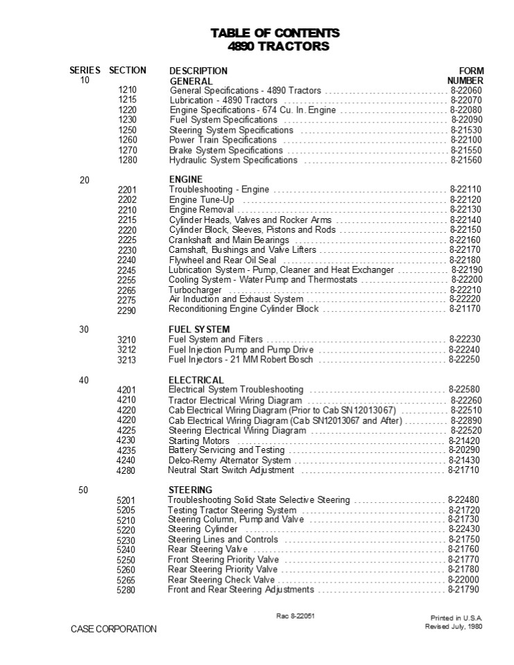
TABLE OF CONTENTS 4890 TRACTORS DESCRIPTION
GENERAL
SERIES 10
SECTION
FORM NUMBER
1210 1215 1220 1230 1250 1260 1270 1280
General Specifications - 4890 Tractors
...............................
8-22060 Lubrication - 4890 Tractors
......................................... 8-22070
Engine Specifications - 674 Cu. In. Engine
........................... 8-22080 Fuel System
Specifications ...................................
...... 8-22090 Steering System Specifications
.....................................
8-21530 Power Train Specifications
.........................................
8-22100 Brake System Specifications
........................................
8-21550 Hydraulic System Specifications
.................................... 8-21560
20
ENGINE Troubleshooting - Engine
...........................................
8-22110 Engine Tune-Up ..........................
......................... 8-22120 Engine Removal
..................................................
.. 8-22130 Cylinder Heads, Valves and Rocker Arms
............................ 8-22140 Cylinder
Block, Sleeves, Pistons and Rods
........................... 8-22150 Crankshaft
and Main Bearings ................................
...... 8-22160 Camshaft, Bushings and Valve
Lifters ................................
8-22170 Flywheel and Rear Oil Seal
.........................................
8-22180 Lubrication System - Pump, Cleaner and
Heat Exchanger ............. 8-22190 Cooling
System - Water Pump and Thermostats
...................... 8-22200 Turbocharger
..................................................
.... 8-22210 Air Induction and Exhaust System
...................................
8-22220 Reconditioning Engine Cylinder Block
............................... 8-21170
2201 2202 2210 2215 2220 2225 2230 2240 2245 2255
2265 2275 2290
30
FUEL SYSTEM Fuel System and Filters
.............................................
8-22230 Fuel Injection Pump and Pump Drive
................................ 8-22240 Fuel
Injectors - 21 MM Robert Bosch ...................
............. 8-22250
3210 3212 3213
ELECTRICAL Electrical System Troubleshooting
..................................
8-22580 Tractor Electrical Wiring Diagram
................................... 8-22260 Cab
Electrical Wiring Diagram (Prior to Cab
SN12013067) ............ 8-22510 Cab Electrical
Wiring Diagram (Cab SN12013067 and After)
........... 8-22890 Steering Electrical Wiring
Diagram ..................................
8-22520 Starting Motors .........................
........................... 8-21420 Battery
Servicing and Testing ............................
........... 8-20290 Delco-Remy Alternator System
......................................
8-21430 Neutral Start Switch Adjustment
.................................... 8-21710
40
4201 4210 4220 4220 4225 4230 4235 4240 4280
50
STEERING Troubleshooting Solid State Selective
Steering ....................... 8-22480 Testing
Tractor Steering System ..........................
.......... 8-21720 Steering Column, Pump and
Valve ..................................
8-21730 Steering Cylinder .......................
........................... 8-22430 Steering
Lines and Controls ..............................
.......... 8-21750 Rear Steering Valve
................................................
8-21760 Front Steering Priority Valve
........................................
8-21770 Rear Steering Priority Valve
.........................................
8-21780 Rear Steering Check Valve
..........................................
8-22000 Front and Rear Steering Adjustments
................................ 8-21790
5201 5205 5210 5220 5230 5240 5250 5260 5265 5280
Rac 8-22051
Printed in U.S.A. Revised July, 1980
CASE CORPORATION
2
SERIES 60
SECTION 6201 6205 6220 6230 6235 6240 6245 6250 62
60
DESCRIPTION POWER TRAIN Troubleshooting - RPS-34
Power Shift Transmission and PTO
FORM NUMBER ........ 8-20370
Testing RPS-34 Power Shift Transmission and PTO
.................. 8-21800 Torque Limiter Clutch
..............................................
8-22270 RPS-34 Power Shift ......................
.......................... 8-22280 RPS-34 Control
Valve and Linkage ................................
.. 8-21830 Four Speed Transmission
...........................................
8-22290 Hydraulic PTO ............................
......................... 8-21850
Axles and Planetaries ............................
................... 8-21860 Differentials and
Drive Shifts .....................................
... 8-21870 BRAKES Brake Pedal, Master Cylinder,
Service and Parking Brake .............
8-21880 HYDRAULICS Troubleshooting - Hitch System
.....................................
8-21890 Testing Tractor Hydraulic System
...................................
8-21900 Hydraulic Oil Filters ....................
............................ 8-21910 Hydraulic
Pump .............................................
....... 8-21920 Remote Hydraulic Valves
...........................................
8-21930 Flow Divider and PTO Control Valve
................................. 8-21940 Hitch
System ..........................................
............ 8-21950 Break-Away Couplings and
Portable Cylinder ........................
8-20640 ACCESSORIES Troubleshooting - Air
Conditioning System ..........................
8-22300 Gauging and Testing Air Conditioning
System ....................... 8-22310 Compressor
Isolation, Removal, Installation and Evacuation
- Discharging, Evacuation and Charging the A. C.
System .............. 8-22320 Servicing Air
Conditioner Components ...........................
... 8-21990 Servicing the Cab Blower
...........................................
8-20690 Operators Seat Adjustments
........................................
8-20700 Removal of Tilting Hood, Grille and Side
Panels ...................... 8-22340 Safety
Decal Location ...................................
........... 8-22500
70
7210
80
8202 8205 8210 8225 8250 8255 8280 8290
90
9205 9215 9225
9235 9245 9250 9260 9280
100
HOW IT WORKS Tractor Steering System
............................................
8-22020 Case Solid State Selective Steering
..................................
8-22490 Tractor Hydraulic System
...........................................
8-22030 Case CON TROL Hydraulics
....................................... 8-21350
15201 15205 18201 18225
Rac 8-22051
Revised 7-80
Printed in U.S.A.
3
Section
121
GENERAL SPECIFICATIONS 4890 Tractors
Written In And English
CASE CORPORATION
Printed in U.S.A. August, J979
4
https//www.ebooklibonline.com Hello dear
friend! Thank you very much for reading. Enter
the link into your browser. The full manual is
available for immediate download. https//www.ebo
oklibonline.com
5
1210-2
SERIAL NUMBERS
ENGINE SERIAL NUMBER PLATE
MODEL AND PRODUCT IDENTIFICATION NUMBER PLATE
- FU LL
CAB SERIAL NUMBER PLATE
TRANSMISSION SERIAL NUMBER PLATE
AXLE SERIAL NUMBER PLATE (Front and Rear)
Issued 8-79
Printed in U.S.A.
Rac 22060
6
12J0-3 HAND SIGNALS For communication under noise
conditions and special operations the Ameri- can
Society of Agricultural Engineers has made
standard agricultural hand signals. You will find
that the hand signals can deCrease time toss and
prevent accidents. Start the Engine This Far To
Go
This far to go Put your Danas n front a. your
face with the oack of your hanos out ward Move
your hands in or out as an inot- cation how far
to go Move OMt
Stop the Engine
Move out face in the neeaed drecton of movement
Pvt your arm straight out oe- Mao you Tnen.
swing your arm over your heaa and forwaro unt
your arm is straight out In front of you witn tne
oack of your
Stoo the engine. Move your rgnt arm across your
neck from left to right
Move Toward Me - Follow Me
Move towara me or follow me Look towaro oerson or
ver c e you need to move. Hold one hano n front
of you with the back of the hand toward the
vehicle and move your arm from the etoow to the
fingers backward and forward
Issued 8-79
Printed n U S.A.
Rac 8 22060
7
Section
2202
ENGINE TUNE-UP
Written In Clear And Simple English
CASE CORPORATION
Rac 8-22120
Printed in U.S.A. August, 1979
8
2202-5
ENGINE TUNE-UP PROCEDURE Checking Top Center STEP
3 TIMING POINTER
STEP 1
TIMING POINTER
Check the push rods on the No 1 cylinder for
looseness If the push rods are tight, turn the
engine over one revolution STEP 4
Turn the engine over until the 20 before TC mark
on the crankshaft pulley is aligned with the
timing pointer STEP 2
Remove the rocker arm assembly STEP 5
Remove the tube between the turbocharger and the
intake manifold Remove the valve cover from the
front cylinder head
Remove the wear cap from the intake valve on
the No 1 cylinder
Issued 8-79
Printed in U S A
Rac 8-22120
9
2202-6 STEP 6
STEP 9
Put a dial indicator on the end of the valve stem
Install the compression tool and bushing, see
Page 4
STEP 10
NOTE Use the mounting bolt for the
center rocker arm to fasten the compression
tool STEP 7
Turn the engine clockwise until the dial
indicator hand stops moving Reset the indicator
hand to zero
Compress the valve springs and remove the valve
keepers Remove the compression tool
Next turn the engine over clockwise, approxi-
mately 5 degrees, until 0 010 (0 254 mm) shows
on the dial indicator Make a mark on the crank-
shaft pulley in line with the timing pointer
STEP 8
Then, turn the engine over counterclockwise, past
the zero mark on the dial indicator, until 0 010
(0 254 mm) shows on the dial indicator Make a
mark on the crankshaft pulley in line with the
timing pointer
Remove the valve rotor and springs
Issued 8-79
Printed in U S A
Rac 8-22120
10
2202-7
STEP 11
STEP 14
Half the distance between the two marks on the
crankshaft pulley will be the Top Center (TC)
mark If the TC mark is not the same as the mark
on the timing tape, remove the timing tape
install the timing tape in line with the TC mark
on the crank- shaft pulley
Compress the valve springs, see Step 6 and
install the valve keepers (narrow end down) in
the groove on the valve stem Then, remove the
com- pression tool and lightly hit the end of the
valve stem to seat the keepers
STEP 12
With the close coil end of the springs down,
install the inner and outer valve springs STEP 13
Put the valve rotator on top of the springs
Issued 8-79
Printed in U S A
Rac 8-22120
11
2202-8
Adjusting Rocker Arm To Valve Clearance STEP
16 Turn the engine over one complete revolution
and align the timing pointer with the TC mark on
the crankshaft pulley
STEP 15
Check and adjust the intake and exhaust valves as
shown by the arrows below Valve Clearance -
Intake Valves 0 014 (0 35 mm) Exhaust Valves 0
031 (0 80 mm) FAN
Check and adjust the intake and exhaust valves as
shown by the arrows below
Valve Clearance - Intake Valves 0 014 (0 35
mm) Exhaust Valves 0 031 (0 80 mm)
NUMBER SIX CYLINDER TOP CENTER COMPRESSION STROKE
FAN
IMPORTANT Valve clearance adjustments must be
made when the engine is not running and the
engine has to cool down a minimum of 1y2 hour
after shutoff
0
O
O
_at_
NUMBER ONE CYLINDER TOP CENTER COMPRESSION STROKE
Checking Fuel Injector Nozzles STEP 18
STEP 17
Remove the fuel supply and return lines to the
injectors
Remove and test each fuel injector See Section
3213 in this Service Manual for testing
NOTE Make a compression test on each cylinder
before installing the injectors.
Issued 8-79
Printed in U S A
Rae 8-22120
12
2202-9
Checking Engine Compression
STEP 19 There are two methods of checking the
compres- sion pressure The two methods are the
crank method and the engine running method The
en- gine must be at operating temperature for
either method used
STEP 22
1 CRANK METHOD - Remove all of the fuel injec-
tors
TURN CLOCKWISE
2 RUNNING METHOD - Disconnect the high
pressure fuel line and leak off line from the
Number One injector Send the fuel from the lines
back to the fuel tank or into a clean con- tainer
Repeat for each cylinder
Always turn the tool clockwise Turning the tool
counterclockwise will damage the tool After using
the tool, clean the injector bores with
compressed air
CAUTIO N Before cramming engine.maIe sure all
operating controls are in neutral, braIes are
set and wheels are securely bIocIed.
STEP 23
STEP 20
TOOL
Install a new injector washer in the cylinder
head bore
Remove the injector washer from the engine bore
See Page 4 for washer removal tool specifications
STEP 24
lnstall compression gauge adapter (70-0301) in
the cylinder head bore
Using bore cleaning tool CAS-10003, clean the
injector bores in the cylinder head Rac 8-22120
lssued 8-79
Printed in U S A
13
2202-10 STEP 25
STEP 27 NOTE Take several compression
readings on each cylinder using the button on
the compression gauge to decrease gauge pressure.
See the chart below for correct compression
pressure.
When checking the compression, using the crank
method, start at the Number One cylinder and con-
tinue down the line (Number 2,3, 4, etc ) Then,
check again the Number One cylinder after finish-
ing the last cylinder, since compression
can change because of a weak battery
It is very important that all cylinder pressures
be approximately the same See the chart for
permit- ted compression pressure differences
Use the retainer nuts for the injector to hold
the compression gauge adapter in place Tighten
the retainer nuts to 7 ft lbs (9 Nm) STEP 26
More than normal compression is an indication of
carbon deposits Below normal compression is an
indication of a valve that leaks or too much ring
clearance
NOTE To make an easy test when the compres- sion
is below normal on one or more cylinders, put
about 1f4 ounce of oil in the cylinder and check
the compression again. If the pressure goes up to
near normal, then the compression loss is past
the rings Very little change in compression is an
indi- cation of leakage past the valves Remove
compression gauge, gauge adapter and injector
washer from the cylinder head Install the
compression gauge (70-0003) on the adapter
ENGINE SPEED NORMAL COMPRESSION PRESSURE PERMITTED CHANGE BETWEEN CYLINDERS
CRANK METHOD APPROXIMATELY 200 RPM UNTIL COMPRESSION GAUGE BECOMES CONSTANT 400 PSI (2758 kPa)(27.58 bar) 25 PSI (172 kPa)(1.72 bar)
RUNNING METHOD 800 RPM 480 PSI (3310 kPa)(33.10 bar) 20 PSI (138 kPa)(1.38 bar)
NOTE A 40/g REDUCTION IN PSI MUST BE PERMITTED
FOR EVERY 1000 FT LEVEL.
(305 mm) ABOVE SEA
Issued 8-79
Printed in U S A
Rac 8-22120
14
2202-11
STEP 29
STEP 28
Install the fuel injectors See Section 3213 in
this Service Manual for installation
Install a new injector washer in the cylinder
head bore
Issued 8-79
Printed in U S A
Rae 8-22120
15
2202-12
Timing The Fuel Injection Pump
Cleaning And Servicing The Air Intake System STEP
30
STEP 32
See Section 2275 in this Service Manual for
clean- ing and servicing the air intake system
See Section 3212 in this Service Manual for
check- ing and adjusting the timing of the fuel
pump
Servicing The Fuel Filters STEP 31
Checking Fuel Injection Pump Governed Speed
See Section 3210 in this Service Manual for
servic- ing the fuel filters See Section 3212 in
this Service Manual for check- ing and adjusting
the governed speed of the fuel injection pump
Issued 8-79
Printed in U S A
Rae 8-22120
16
2202-13
Adjusting Fan And Compressor Belts STEP 36
STEP 34 BELT TENSION GAUGE
BELT TENSION GAUGE
Measure the fan belts for the correct tension Use
a belt tension gauge Belt tension must be 60 lbs
(267 N) per belt DO NOT go over a total tension
of 140 lbs (628 N) on the belts
CRANKSHAFT PULLEY COMPRESSOR PULLEY Measure the
compressor belt for the correct ten- sion Use a
belt tension gauge Belt tension must be 80 lbs
(355 N)
NOTE See Section 9235 in this Service Manual for
tension and alignment adiustments.
STEP 35
ADJUSTING LUG
FAN BELTS To adjust the belts, loosen the
alternator adjusting and mounting bolts Use a
3/4 inch open end wrench (or 19 mm) on the upper
adjusting lug on the alternator Pull the
alternator outward until the correct tension is
reached then, tighten the bolts NOTE See
Section 2255 in this Service Manual for
installing and adjusting new fan belts.
Rac 8-22120
Issued 8-79
Printed in U S A
17
2202-14
Checking Valve Timing
NOTE This procedure can also be used to check
for the correct assembly of the camshaft to the
crankshaft gear teeth without removing the front
timing gear cover
sTEP 39
STEP 37
TIMING POINTER
Make sure the valve tappet clearance on the
intake valve is correct, 0 014 (0 35 mm) STEP
40 Turn the engine over until the timing pointer
is aligned with the TC mark on the crankshaft
pulley STEP 38
Put a dial indicator on the Number One intake
valve retainer and set the dial indicator at
zero STEP 41
Check the Number One intake and exhaust valve
push rods, the push rods must be loose If the
push rods are tight, turn the engine over one
complete revolution
Turn the engine over clockwise one complete rev-
olution The dial indicator must show a reading of
2 1 to 3 1 mm for the correct valve timing If the
2 1 to 3 1 mm reading is not reached, the
complete valve train assembly must be checked
Issued 8-79
Printed in U S A
Rac 8-22120
18
Section
2210
ENGINE REMOVAL
Written In Clear
And
Simple
English
Printed in U.S.A. August, 1979
Rae 8-22130
CASE CORPORATION
19
2210-2
ENGINE REMOVAL
The instructions in this section are for the
removal of the engine with the radiator and front
casting as one complete assembly as shown. The
engine is removed from the tractor at the torque
tube. Removal of the engine at the torque tube
will permit servicing the following
items Torque Limiter Engine Flywheel PTO Drive
Shaft Power Shift Engine Crankshaft Engine Rear
Oil Seal Engine Camshaft Rear Bushing Transmission
Intermediate Shaft Front Bearing
Rac 8-22130
Issued 8-79
Printed in U.S.A.
20
2210-3
STEP 1
STEP 3
HOOD
GRILLE SIDE PANELS
RADIATOR DRAINCOCK
Remove the hood, side panels and grille from the
tractor. See Section 9260 for instructions. ENGINE
BLOCK DQ STEP 2 AIR INDUCTION SYSTEM
Drain the coolant from the radiator and engine
block. STEP 4
Remove the air induction system from the engine.
See Section 2275 for instructions.
Remove the pyrometer sensing unit.
Issued 8-79
Printed in U.S A.
Rac 8-22130
21
2210-4
STEP 8
STEP 5
Disconnect the tachometer cable from the engine.
Remove the turbocharger exhaust coupling bolts.
STEP 9
STEP 6
REMOVE U-BOLTS
Remove the battery ground cables (negative-
black) from the starting motor.
Remove the u-bolts from the exhaust tube
and support bracket.
STEP 10
STEP 7
REMOVE BRACKET
Remove the battery positive (red) cables from the
solenoid switch of the starting motor.
Remove the support bracket from the engine
block.
Issued 8-79
Printed in U.S.A.
Rac 8-22130
22
2210-5
STEP 14
STEP 11
Disconnect the air conditioning return hose from
the compressor.
Put tape on the ends of the positive (red)
battery cables to prevent a spark that can be
caused by an accident.
STEP 15
STEP 12
FUEL RETURN LINE
FUEL SUPPLY ONE g
Disconnect the cab heater hose from the engine
oil cooler to water pump tube.
Disconnect the fuel supply and return lines from
the fuel pump.
STEP 16
STEP 13
Disconnect the air conditioning pressure
hose from the receiver-drier.
Disconnect the fuel pump throttle and engine stop
cables from the fuel pump and bracket.
Issued 8-79
Printed in U.S.A.
Rac 8-22130
23
Suggest If the above button click is invalid.
Please download this document first, and then
click the above link to download the complete
manual. Thank you so much for reading
24
2210-6
STEP 20
STEP 17
REMOVE BOLT
Remove the retaining bolt for the wiring harness
connector.
Disconnect the engine harness blue-g reen con-
nectors.
STEP 21
STEP 18
Disconnect the engine harness pink-yellow con-
nectors.
Pull the wiring harness connector from the
firewall connector.
STEP 22
STEP 19
Disconnect the engine harness single green to the
double green connectors.
Disconnect the engine harness connector from the
transmission harness connector.
Issued 8-79
Printed in U,S.A.
Rae 8-22130
25
https//www.ebooklibonline.com Hello dear
friend! Thank you very much for reading. Enter
the link into your browser. The full manual is
available for immediate download. https//www.ebo
oklibonline.com
Recommended
