
Volvo MC80B Skid Steer Loader Service Repair Manual Instant Download PowerPoint PPT Presentation
Title: Volvo MC80B Skid Steer Loader Service Repair Manual Instant Download
1
Service Information
Document Title Engine Tier 3 introduction Function Group 200 Information Type Service Information Date 2014/3/19
Profile SSL, MC80B GB Profile SSL, MC80B GB Profile SSL, MC80B GB Profile SSL, MC80B GB
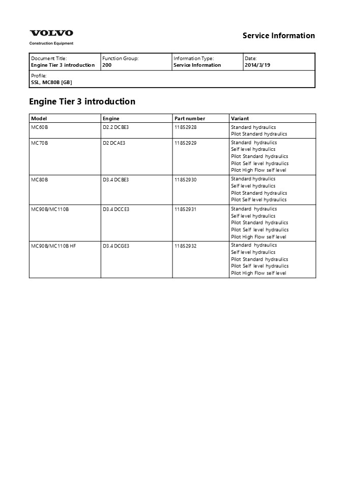
Engine Tier 3 introduction
Model Engine Part number Variant
MC60B D2.2 DCBE3 11852928 Standard hydraulics Pilot Standard hydraulics
MC70B D2 DCAE3 11852929 Standard hydraulics Self level hydraulics Pilot Standard hydraulics Pilot Self level hydraulics Pilot High Flow self level
MC80B D3.4 DCBE3 11852930 Standard hydraulics Self level hydraulics Pilot Standard hydraulics Pilot Self level hydraulics
MC90B/MC110B D3.4 DCCE3 11852931 Standard hydraulics Self level hydraulics Pilot Standard hydraulics Pilot Self level hydraulics Pilot High Flow self level
MC90B/MC110B HF D3.4 DCGE3 11852932 Standard hydraulics Self level hydraulics Pilot Standard hydraulics Pilot Self level hydraulics Pilot High Flow self level
2
Service Information
Document Title Engine for MC80B, MC90B and MC110B, description Function Group 200 Information Type Service Information Date 2014/3/19
Profile SSL, MC80B GB Profile SSL, MC80B GB Profile SSL, MC80B GB Profile SSL, MC80B GB
Go back to Index Page Engine for MC80B, MC90B
and MC110B, description The engine is a vertical
in-line, four cylinder, four stroke, water-cooled
diesel engine with a direct injection system. The
engines for MC90B and MC110B are also equipped
with a turbocharger of radial flow type. The
valve mechanism receives its movement from the
camshaft via rods and rocker arms. Turning
direction is counter-clockwise seen from the
flywheel. Firing order is 1-3-4-2 and the first
cylinder is on the flywheel side. The fuel system
is direct injection via a rotary high pressure
pump, a so called MP pump. The pump has only one
plunger cylinder to pressurize the fuel and a
distribution shaft which regulates the fuel flow
to each cylinder. The lubrication system consists
of forced lubrication with a trochoid pump. The
air system consists of a dual element, self
cleaning air cleaner. The cooling of the engine
is performed by a high capacity radiator and a
hydraulic oil cooler. The type of fluid used in
the cooling system consists of 50 ethylene
glycol and 50 water, which gives an anti-freeze
protection.
Figure 1 Engine, MC80B (Volvo D3.4A CAE2SW3U)
Figure 2 Engine, MC90B and MC110B (Volvo D3.4A
CAE2SW1U, engine with high flow Volvo D3.4A
CAE2SW2U)
3
Service Information
Document Title Engine, description Function Group 200 Information Type Service Information Date 2014/3/19
Profile SSL, MC80B GB Profile SSL, MC80B GB Profile SSL, MC80B GB Profile SSL, MC80B GB
Go back to Index Page Engine, description MC80B
(D3.4DCAE2) The engine is a vertical in-line,
four cylinder, four stroke, water-cooled diesel
engine with a direct injection system. The valve
mechanism receives its movement from the camshaft
via rods and rocker arms. Turning direction is
counter-clockwise seen from the flywheel. Firing
order is 1-3-4-2 and the first cylinder is on the
flywheel side. The fuel system is fed by an
electric fuel pump that supplies the fuel to the
electronic fuel injection pump. The lubrication
system consists of forced lubrication with a
trochoid pump. The air system consists of a dual
element, self cleaning air cleaner. The cooling
of the engine is performed by a high capacity
radiator and a hydraulic oil cooler.
Figure 1
4
https//www.ebooklibonline.com Hello dear
friend! Thank you very much for reading. Enter
the link into your browser. The full manual is
available for immediate download. https//www.eb
ooklibonline.com
5
Service Information
Document Title E-ECU, MID 128, changing non-programmed ECU Function Group 200 Information Type Service Information Date 2014/3/19
Profile SSL, MC80B GB Profile SSL, MC80B GB Profile SSL, MC80B GB Profile SSL, MC80B GB
E-ECU, MID 128, changing non-programmed ECU Op
nbr 200-068 VCADS Pro VCADS Pro Service Tool
88890180 Interface 88890027 Cable This operation
also includes required tools and times for
applicable parts of the following operations
191 Service position 1
?
- Place the machine in service position, see 191
Service position 1. - Connect VCADS Pro and start the operation 28423-3
MID 128 ECU, programming. - Unplug the connectors from E-ECU.
- Figure 1 E-ECU
- Change E-ECU.
- Plug in the connector.
- Turn on the voltage with the battery disconnect
switch. - Finish VCADS Pro operation 28423-3 MID 128 ECU,
programming. - Start the machine and check that no error
messages appear. - Restore the machine to operating condition.
6
Service Information
Document Title E-ECU, MID 128, changing pre-programmed ECU Function Group 200 Information Type Service Information Date 2014/3/19
Profile SSL, MC80B GB Profile SSL, MC80B GB Profile SSL, MC80B GB Profile SSL, MC80B GB
E-ECU, MID 128, changing pre-programmed ECU Op
nbr 200-070 VCADS Pro VCADS Pro Service Tool
88890180 Interface 88890027 Cable This operation
also includes required tools and times for
applicable parts of the following operations
191 Service position 1
?
- Place the machine in service position, see 191
Service position 1. - The new control unit has basic set parameters for
the machine. If it is possible to read out
customer parameters, connect VCADS Pro and start
the operation 17030-3 Parameter, programming.
Save all read parameters to job card. The
operation is used to read out customer parameters
from the old control unit to enable later
comparison with parameters in the new control
unit. - Unplug the connector from E-ECU.
- Figure 1 E-ECU
- Change E-ECU.
- Plug in the connector.
- Turn on the voltage with the battery disconnect
switch. - If customer parameters have been read out from
the old control unit, compare these to the
parameters in the new control unit. - Connect VCADS Pro and perform the operation
17030-3 Parameter, programming. Save all read
parameters to job card. - Compare parameter settings on the job cards.
7
- Perform operation 17030-3 Parameter, programming
and change customer parameters according to job
card for the old control unit. - Start the machine and check that no error
messages appear. - Restore the machine to operating condition.
8
Service Information
Document Title Engine, removing Function Group 210 Information Type Service Information Date 2014/3/19
Profile SSL, MC80B GB Profile SSL, MC80B GB Profile SSL, MC80B GB Profile SSL, MC80B GB
Engine, removing Op nbr 210-070 11668023 Lifting
tool 9993902 Disassembly tool 9993903
Disassembly tool
WARNING
- Hot oil and hot engine coolant can cause severe
burns! - Put the machine in service position 1, see 191
Service position 1. - Turn off the electric power with the battery
disconnect switch.
NOTICE
Always handle oils and other environmentally
hazardous fluids in an environmentally safe
manner. 3. Open the drain valve and drain the
coolant into a suitable container. Volume,
approx. 10 l (2.7 US gal)
Figure 1 4. Carefully open the filler cap on
the radiator to speed up the draining.
9
- Figure 2
- 1. Radiator cap
- When the radiator is drained, close the drain
valve. - Disconnect the lower end of the gas spring.
Figure 3 1. Gas spring 7. Remove the engine
cover from the crossmember.
10
Figure 4 1. Engine cover mounting 8.
Disconnect the radiator overflow hose from the
radiator and drain the overflow bottle into a
container.
- Figure 5
- Radiator fill cap
- Over flow hose
- Over flow bottle
NOTICE
Always handle oils and other environmentally
hazardous fluids in an environmentally safe
manner. Applies to engines equipped with High
flow Open the hydraulic fluid drain plug and
drain the hydraulic fluid into a suitable
container (approx. 70 l, 18.5 US gal)
11
Figure 6 1. Hydraulic fluid drain plug beneath
the left hand tower 9. Disconnect the return
hose from the main hydraulic oil filter. Drain
the oil cooler via the hose into a container.
Plug the connections.
- Figure 7
- Main hydraulic oil filter
- Return hose
- 10. Disconnect the support cable from the
hydraulic oil cooler.
12
- Figure 8
- Hydraulic oil cooler
- Radiator
- Support cable
- Latch
- 11. Disconnect the right side swivel connection
from the radiator by sliding the lock washer
inwards.Use 9993902 Disassembly tool and 9993903
Disassembly tool. Use a suitable container to
collect any spillage. Plug the connections.
- Figure 9
- 1. Swivel joint
- Open the latches holding the cooling assembly
together. Lift the oil cooler from the radiator.
Carefully place the oil cooler on a flat
surface. - Weight, approximately 20 kg (44 lb)
- Disconnect the upper radiator hose from the
engine block. Plug the connections.
- Figure 10
- Upper radiator hose
- Fan guard
- Lower radiator hose
13
- Disconnect the lower radiator hose from the
engine block. - Remove the fan guard from the radiator.
- Remove the screws from the radiator mounts.
Carefully remove the radiator and place the
radiator on a flat surface. Weight, approx. 40
kg (88 lb) - NOTE!
- Use care when handling the radiator.
- To prevent damage to the radiator drain
connection, do not place the radiator on its
bottom surface without support blocks used on
each side.
- Figure 11
- Lower radiator mounts
- Upper radiator mounts
- If the machine is equipped with cab heater,
disconnect the hoses from the water pump.
- Figure 12
- Water pump
- Cab heat hose
- 17. Disconnect the connector from the air cleaner
restriction sensor.
14
Figure 13 1. Air cleaner restriction sensor 18.
Disconnect the air intake hose from the engine
intake manifold
- Figure 14
- Engine without Turbo
- Air intake hose
- Engine intake manifold
NOTICE
Always cover open air connections with a plastic
bag and rubber bands. Gravel, dust and other
particles in these connections may result in
engine failure! If the machine is equipped with
turbo, disconnect the air intake hose from the
turbo.
15
- Figure 15
- Engine with turbo
- Air intake hose
- Turbo
- Remove the air cleaner assembly from the mounting
bracket. - Remove the exhaust pipe between the exhaust
manifold and the muffler. Plug the exhaust
manifold.
- Figure 16
- Engine without turbo
- Exhaust pipe
- Exhaust manifold
- Muffler
- Tail pipe
- If the machine is equipped with turbo, remove the
exhaust pipe between the turbo and the muffler.
Plug the connections to the turbo.
16
- Figure 17
- Engine with turbo
- Exhaust pipe
- Turbo
- Muffler
- Tail pipe
- Remove the muffler out of the engine compartment
- Disconnect the engine harness from the chassis
harness.
Figure 18 1. Chassis harness connector to
engine 23. Disconnect the preheater wire from
the engine.
Figure 19 1. Preheater wire 24. Disconnect the
throttle cable from the fuel injection pump lever.
17
- Figure 20
- Throttle cable
- Fuel injection pump lever
- Clamp
- 25. Tag and disconnect the cables from the
starter soleniod. Tag and disconnect the ground
wires from the starter flange.
- Figure 21
- Starter
- Positive (B)
- Manoeuvre
- Ground
- 26. Close the valve on the fuel supply line at
the water separator.
18
- Figure 22
- Water separator
- Valve
- Fuel supply line
- 27. Tag, disconnect and plug the fuel supply and
fuel return line from the engine.
- Figure 23
- Fuel supply line
- Fuel return line
- Applies to machines equipped with AC
NOTICE
Refrigerant under pressure. Do not disconnect any
hoses or connections on the air conditioning,
thereby involuntary releasing refrigerant. 28.
Slightly loosen the screws holding the compressor
to the mounting bracket and pivot the compressor
towards the engine. Remove the belt from the
crankshaft pulley.
- Figure 24
- Crankshaft pulley
- Compressor
19
29. Release the hoses between the compressor and
the AC unit from the clamp.
- Figure 25
- AC unit hoses
- Disconnect the connector from the AC.
- Remove the compressor from the mounting bracket
and put it aside.
Figure 26 Applies to engines equipped with High
flow 32. Tag, remove and plug the hoses from
the high flow pump.
20
Suggest If the above button click is invalid.
Please download this document first, and then
click the above link to download the complete
manual. Thank you so much for reading
21
Figure 27 1. High flow pump connection Continued
NOTE! The engine must be lifted from the
machine using an overhead hoist, rated at a
minimum capacity of 500 kg (1100 lb). 33.
Connect the lifting tool 11668023 to the front
and rear lift eyes. Remove all slack in the lift
equipment to prevent the engine from unintended
movement during removal.
- Figure 28 Lifting tool
- Remove screws, bushings and nuts from the rear
and front engine mount. - Lift and move the engine slightly toward the rear
of the machine until the transmission universal
drive joint drops free of the splined
transmission drive shaft.
- Figure 29
- Transmission universal drive joint
- Splined transmission drive shaft
- NOTE!
- Weight approximately 340 kg (750 lb).
- Slowly and carefully lift the engine from the
machine. - Place the engine on engine stands or similar,
strong and stable enough to support the weight of
the engine.
22
https//www.ebooklibonline.com Hello dear
friend! Thank you very much for reading. Enter
the link into your browser. The full manual is
available for immediate download. https//www.eb
ooklibonline.com
Recommended
