

TOYOTA FBMF16 FBMF20 FBMF25 FBMF30 Forklift Service Repair Manual Instant Download PowerPoint PPT Presentation
Title: TOYOTA FBMF16 FBMF20 FBMF25 FBMF30 Forklift Service Repair Manual Instant Download
1
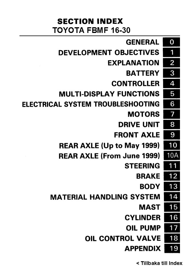
TOYOTA FBMF 16-30
lt Tillbaka till Index
2
This manual covers the service proceduras of the
TOYOTA BATTERY FORKLIFT FBMF18 - 30 Series.
Please use this manual for providing quick,
correct servicing of the corresponding forklift
models. This manual deals with the above models
as of June 1996. Please understand that
disagreement can take place between the
descriptions in the manual and actual vehicles
due to change in design and specifica- tions.
Any change or modifications thereafter will
be informed by Toyota Industrial Vehicles'
Parts Service News. TOYOTA MatarialHandling
Company
3
TOTALDOKUMENT, SERVICE ...........................
.. 0-23
4
https//www.ebooklibonline.com Hello dear
friend! Thank you very much for reading. Enter
the link into your browser. The full manual is
available for immediate download. https//www.ebo
oklibonline.com
5
EXTERIOR VIEWS
6
0-3
VEHICLE MODELS
Model ltem Model ltem FBMF16 FBMF2O FBMF25 FBMF3O
Load capacity kg (lbl Load capacity kg (lbl 1600 (32OOl 2000 (4OO0l 2500 (SOOOI 3000 í6OO0
Voltage V Voltage V 72/80
Battely capacity AH/5H STD capacity 360 480 600
Battely capacity AH/5H Max. capacity 450 600 750
FRAME NUMBER
Model FBMF16 FBMF2O-25 FBMF3O
Punching format FBMF 16 _at_ 10001 FBMF25 _at_
10001 FBMF3O 10001
7
LIST OF REFERENCE PAGES IN PUBLISHED NEW MODEL
FEATURES The FBMF 16, 2O, 25 and 3O are based on
the body for FBM 16 to 3O. For the sections not
included in this manual, please refer to the
published new model features for the FBM16 to 3O
(No. PE3O1 ). This list shows the reference pages
for each section.
Item (published new model faatures for the FBM16 to 30) Item (published new model faatures for the FBM16 to 30) FBMF16 20 25 30
ELECTRICAL SYSTEM BATTERY CHARGER ACCELERATOR DRIVE MOTOR PUMP MOTOR POWER STEERING MOTOR CONTROLLER 2-2 2-5
POWER TRAIN DRIVE UNIT
FRONT AXLE
REAR AXLE 2-6
DRIVE, STEERING AND BRAKE SYSTEM WHEELS 2-7
STEERING 2-8
BRAKE 2-8
FRAME AUXILIARY EOUIPMENT BODY FRAME LAMPS SWITCHES INSTRUMENTS Digital Multi-Display 2-10 2-12 2-12
Diagnosis Analyzer
V MAST 2-13
FV MAST IOPTI 2-14
FSV MAST (OPT) 2-J 4
FORK BACKREST 2-15
MATERIAL HANDLING AND MAST INTERCHANGEABILITY 2-16
HYDRAULIC SYSTEMS LIFT CYLINDER 2-17
TILT CYLINDER 2-20
OIL PUMP 2-21
OIL CONTROL VALVE
HYDRAULIC CIRCUIT 2-22
- Only the modified points are described.
8
0-5
- HOW TO READ THIS MANUAL
- EXPLANATION METHOD
- Operation procedure
- The operation procedure is described in either
pattern A or pattern B below. Pattern
A Explanation of each operation step with
illustration. - Pattern B Explanation of operation procedure by
indicating step numbers in one illustration,
followed by explanation of cautions and notes
summarized as point operations. - Example of description in pattern B
Tightening torque unit T - N-m (kgf-cm) fft-lbfl
DISASSEMBLY-INSPECTION-REASSEMBLY
If a place or part cannot be indicated directly,
the gart name is described on the either side of
the illustration. 7 I4 7O 4901 134. Xf
25.451
- Disasaembly Procedure
- Remove the cover. Point 1Ip
- Remove the bush. lPoint 2- Operation explained
later - Remove the gear.
- Point operations
Explanation of key point for operation with an
illustration
IPoint 1 / Disassembly Put a match mark when
removing the pump cover. IPoint
2) Inspection Measure the bush inside
diameter. Bush inside diameter limit I 9.12 mm
(0.7528 in)
9
0-6
- How to read components figures
- The components figure uses the illustra- tion in
the parts catalog for the vehicle model. Please
refer to the catalog for checking the part name. - The number at the right shoulder of each
components figure indicates the Fig. num- - ber in the parts catalog.
(Examplel
3201
FIG number in parts catalog
- Matters omitted in this manual
- (1T This manual omits description of the
following jobs, but perform them in actual
operation - Cleaning and washing of removed parts as required
- Visual inspection lpartially described)
- TERMINOLOGY
- Caution
- Important matters of which negligence may cause
accidents. Be sure to observe them. - Note
- Important items of which negligence may cauee
accidents. or matters in operation procedure re-
quiring special attention. - Standard Values showing allowable range in
inspection and adjustment. Limit Maximum or
minimum allowable value in inspection or
adjustment. - ABBREVIATIONS
Abbreviation (code) Meaning Abbreviation (code) Meaning
ASSY Assembly SST Special service tool
LH Left hand STD Standard
LLC Long life coolant T Tightening torque
OPT Option O O T Number of teeth IO O I
O Oversizs U/S Undersize
PS Power steering W/ With
RH Right hand L/ Less
SAE Society of Automotive Engineers fUSA)
10
8-9
- Disassembly Procedure
- Remove the two pick up sensors.
- Remove the drive unit cap.
- Remove the drive gear lock nut. Point 1I
- Remove the tapered roller bearing. (Point 2
- Remove the front axle housing RH. fPoint 3)
- Remove the differential ASSY.
- Remove the reduction gear key plate.
- Remove the front axle housing LH. Point 4)
- Remove the drive gear, reduction gear and output
gear. - Remove the drive gear bearing. (Point 5
- Remove the bearings from the output gear. (Point
6 - Remove the bearings from the reduction gear.
Point 71 - Reassembly Procedure
- The reassembly procedure is the reverse of the
disassembly procedure. - Note
- The tightening torque for each portion is as
follows
Unit
T N-m (kgf-cm) ft-IbfJ
Front axle housing LH set bolt 60.8 - 113.7 (620 11601 (44.9 83.9)
Front axle housing RH set bolt 60.8 - 113.7 1620 - 1160) (44.9 - 83.91
Out put gear lock nut 167 - 226 I1700 - 2300) I123 166J
Drive unit cap set bolt 60.8 - J 13.7 f62O - J J60) 144.9 83.91
11
8-10 Point Operations (Point 1 Disassembly Usin
g a chisel, unstake the nut. Reassembly Using a
punch, stake the nut.
Disassembly Reassembly SST 09330-13200-71
SST
Point 2 Disassembly
- Remove the washer.
- Using SST, remove the tapered roller
- bearing.
- SST 09556-76001-71 (SST 09556-22010)
SST
Reassembly
- Using SST, temporarily install the tapered
roller bearing. - SST 09008-04031
- Install the washer, as shown.
SST
fPoint 3 Disassembly
Use two service bolts for disassembly. Service
bolt size M14 x I .5
Raassembly
Coat liquid gasket on the gear case matching
surface before reassembly. Gasket 08826-76002-71
(08826-00090)
12
8-1 1 Disassembly Using SST, remove the bearing
outer races and spacer. SST 09950-76018-71 (SST
09950-60010) - SST 09950-76020-71 (SST
09950-70010) - Reassembly Using SST, install the
bearing outer races and spacer. SST
09950-76018-71 (SST 09950-600101 SST
09950-76020-71 (SST 09950-7001 0) - fPoint
4) Disassembly Use two service bolts for
disassembly. Service bolt size M 14 x 1.5
Reassembly
Coat liquid gasket on the gear case matching
surface before reassembly. Gasket 08826-OOO9O
Disassembly Using SST, remove the bearings. SST
09950-76004-71 (SST 09950-4001 1) - SST
09950-76018-71 (SST 09950-6001 0) - _at_
SST
If the drive gear bearing remains in the axle
housing LH SST 09308-1OOIO
SST
Reassembly SST 09950-76018-71 (SST 09950-60010)
-_at_ SST 09950-76020-71 (SST 09950-70010) -_at_
SST 2
SST (i)
13
8-12
Disassembly Using SST, remove the tapered roller
bear- SST 09950-76014-71 (SST 09950-4001 1)
ing.
SST
Reassembly Using SST, install the tapered roller
bearing. SST 09608-76003-71 (SST 09608-04031)
SST
SST SST
Disassembly Using a brass bar, remove the
bearing.
Reassembly Using SST, install the bearing. SST
09950-76018-71 (SST 09950-60010) -_at_ SST
09950-76020-71 (SST 09950-70010) -'_at_
14
8-13
DIFFERENTIAL DISASSEMBLYINSPECTION-REASSEMBLY
- Disassembly Procedure
- Remove the differential case bearings. (Point 1
- Remove the ring gear. (Point 2)
- Remove the RH differential case. (Point 3
- Remove the side gears, pinion gears, spider and
thrust washers. Point 4 - Reassembly Procedure
- The reassembly procedure is the reverse of the
disassembly procedure.
Point Operations (Point 1) Disassembly SST
09950-76014-71 (SST 09950-40011)- _at_ SST
09950-76018-71 (SST 09950-60010) --_at_
SST
SST 2
15
8-14 Reassembly SST 09950-76018-71 (SST
09950-60010) SST 09950-76020-71 (SST
09950-70010) -'
SST 2/
SST I)
Point 2
Disassembly
Punch match marks on the ring gear and LH
differential casa.
Reassembly
Align the match marks.
IPoint 3l Disassembly
Punch match marks on the RH and LH dif- ferential
cases.
Align the match marks.
Reassembly
Point 4j Inspection Measure the backlash
between the side gear and pinion gear. Install
the side gear and pinion gear on the case.
Lightly push the spider to bring pinion gear and
side gear close to the thrust washer for
measurement. Backlash 0.2 - O.3 mm (0.008 -
0.0t2 Inl Measure the backlash at both cases.
Inspection Measure the spider outside
diameter. Standard 22.00 mm (0.8661
in) Llmh 21.75 mm (0.8563 in)
16
9-1
FRONT AXLE
Page 9-2 9-3 9-4 9-7
GENERAL ..........................................
.......... SPECIFICATIONS .......................
.................. COMPONENTS ....................
........................ FRONT AXLE SHAFT-HAB
.............................
REMOVALINSTALLATION .............................
....... 9-7
9
17
9-2
GENERAL FBMF16
FBMF2O 25
FBMF3O
18
9-3 SPECIFICATIONS
Item Model FBMF16 FBMF2O 25 FBMF2O 25 FBMF3O FBMF3O
Front axle type Front axle type Full-floating
Suspension type Suspension type Fixed to frame
Axle shaft diameter mm 4O 11.571
Axle shaft diameter Ispline portion) mm (in) Axle shaft diameter Ispline portion) mm (in) 4O (1.571
Wheel (STDI Tire size 21 x 8 9 23 x 9 10 23 x 9 10 28 x 9 - 15
Wheel (STDI Rim size 9 X 6.OOE 10 x 6.5OF 15 x 7.OOT 15 x 7.OOT
Tire inflating pressure
Model Type Rim size Pneumatic shaped cushion tire Pneumatic tire nfIating pressure kPa fkgf/cm2) (psi)
FBMF16 Standard Over size Wide tread 9 x 6.OOE TB 21 x 8 9 21 x 8 9 14PR 6.50 1O 12PR 21 x 8 9 14PR 883 f9.OI f128I
FBMF16 Standard Over size Wide tread 10 x 5.O0F TB 6.50 IO 21 x 8 9 14PR 6.50 1O 12PR 21 x 8 9 14PR 883 f9.OI f128I
FBMF16 Standard Over size Wide tread 9 x 6.OOE TB 21 x 8 9 21 x 8 9 14PR 6.50 1O 12PR 21 x 8 9 14PR 883 f9.OI f128I
FBMF20 25 Standard Wide tread 10 x 6.5OF TB 23 x 9 10 23 x 9 10 18PR 883 19.0) (128)
FBMF30 Standard Wide tread 15 x 7.OOT IR 28 x 9 15 28 x 9 15 14PR 785 18.0) f114)
FBMF30 Standard Wide tread 15 x 7.O0S SDC 28 x 9 15 28 x 9 15 14PR 785 18.0) f114)
FBMF30 Standard Wide tread 15 x 7.OOT IR 28 x 9 15 14PR 785 18.0) f114)
FBMF30 Standard Wide tread 15 x 7.OOS SDC 28 x 9 15 14PR 785 18.0) f114)
19
9-4
COMPONENTS FBMF 16
42O1
FD
94512-01800 AB
AP
42
FD
94512-01800
AD
AB
A
94512-00soo
4 IC 40C
40 /01-139
20
9-5
FBMF20 25
42O1
94512-01800 AB
""
AP 43A y
42
FD 43B
43RL 44(LHJ
AD
94512-01800
41A 41B
AB
41
41E
40
94512-00800 41D
41C 1 49
ES
40C
41J 40D 4f 40B 4201-153
21
9-6
FBMF3O
4201
FWD
94512-01800 AB
43E
AC
43RL 44LH
FD
AD
AP AB 94512-01800
41A 41B
41
40
41C 1
49 94512-00800 41D AE
(WlDE TREAD)
41G
AH
40C
BT
40D
4OA OB 4201-154
AG
22
9-7
FRONT AXLE SHAFT-HUB REMOVAL-INSTALLATION
FBMF16
- Dr ve un
- Rear wheel
- Front wheel hub nut 5 Front wheels
- Removal Procedure
- Drain differential oil.
- Chock the rear wheels.
- Loosen the front wheel hub nuts.
- Jack up the frame and support its bottom with a
stand or wooden blocks. - Remove the front wheels.
- Remove the axle shaft. (Point 1)
- Remove the bearing lock nut and lock nut plate.
(Point 2 - Remove the front axle hub W/brake drum. (Point 3
- Remove the axle shaft oil seal. (Point 4
- Remove the hub oil seal and bearing. Point 51
- Disconnect the brake drum. fPolnt 6J
23
Suggest For more complete manuals. Please go to
the home page. https//www.ebooklibonline.com If
the above button click is invalid. Please
download this document first, and then click the
above link to download the complete manual. Thank
you so much for reading
24
9-8
- Installation Procedure
- The installation procedure is the reverse of the
removal procedure. - Note
- Coat thread tightened (08833-000701 on the brake
drum set nut before tightening. - Adjust the braking performance after
installation. Make the vehicle travel in the
forward and reverse directions about 10 times and
depress the brake pedal to stop the vehicle each
time. - The tightening torque for each portion is as
follows - Unit N m (kgf-cm) lft-lbf)
Brake drum set nut (hub bolt set nut) FBMFJ 6 68.65 - 88.26 (700 - 9D0I (50.65 86.821 FBMF20-25 78.45 - 107.87 (800 - 1100) (57.88 - 79.59) FBMF30 J 68.71 - 205.94 (1700 - 2J 00) (J 23.00 - J 51.941 FBMFJ 6 68.65 - 88.26 (700 - 9D0I (50.65 86.821 FBMF20-25 78.45 - 107.87 (800 - 1100) (57.88 - 79.59) FBMF30 J 68.71 - 205.94 (1700 - 2J 00) (J 23.00 - J 51.941 FBMFJ 6 68.65 - 88.26 (700 - 9D0I (50.65 86.821 FBMF20-25 78.45 - 107.87 (800 - 1100) (57.88 - 79.59) FBMF30 J 68.71 - 205.94 (1700 - 2J 00) (J 23.00 - J 51.941 FBMFJ 6 68.65 - 88.26 (700 - 9D0I (50.65 86.821 FBMF20-25 78.45 - 107.87 (800 - 1100) (57.88 - 79.59) FBMF30 J 68.71 - 205.94 (1700 - 2J 00) (J 23.00 - J 51.941 FBMFJ 6 68.65 - 88.26 (700 - 9D0I (50.65 86.821 FBMF20-25 78.45 - 107.87 (800 - 1100) (57.88 - 79.59) FBMF30 J 68.71 - 205.94 (1700 - 2J 00) (J 23.00 - J 51.941 FBMFJ 6 68.65 - 88.26 (700 - 9D0I (50.65 86.821 FBMF20-25 78.45 - 107.87 (800 - 1100) (57.88 - 79.59) FBMF30 J 68.71 - 205.94 (1700 - 2J 00) (J 23.00 - J 51.941 FBMFJ 6 68.65 - 88.26 (700 - 9D0I (50.65 86.821 FBMF20-25 78.45 - 107.87 (800 - 1100) (57.88 - 79.59) FBMF30 J 68.71 - 205.94 (1700 - 2J 00) (J 23.00 - J 51.941 FBMFJ 6 68.65 - 88.26 (700 - 9D0I (50.65 86.821 FBMF20-25 78.45 - 107.87 (800 - 1100) (57.88 - 79.59) FBMF30 J 68.71 - 205.94 (1700 - 2J 00) (J 23.00 - J 51.941
Bearing lock nut stopper bolt 14.71 - 21.57 NJ 50 220) II 0.85 15.921 14.71 - 21.57 NJ 50 220) II 0.85 15.921 14.71 - 21.57 NJ 50 220) II 0.85 15.921 14.71 - 21.57 NJ 50 220) II 0.85 15.921 14.71 - 21.57 NJ 50 220) II 0.85 15.921 14.71 - 21.57 NJ 50 220) II 0.85 15.921 14.71 - 21.57 NJ 50 220) II 0.85 15.921 14.71 - 21.57 NJ 50 220) II 0.85 15.921
Axle shaft set bolt FBMF2O-25 68.65 - 88.26 f7OO 900) (50.65 - 86.821 FBMF3O 98.07 - 127.49 11000 - 12001172.35 - 94.061 FBMF2O-25 68.65 - 88.26 f7OO 900) (50.65 - 86.821 FBMF3O 98.07 - 127.49 11000 - 12001172.35 - 94.061 FBMF2O-25 68.65 - 88.26 f7OO 900) (50.65 - 86.821 FBMF3O 98.07 - 127.49 11000 - 12001172.35 - 94.061 FBMF2O-25 68.65 - 88.26 f7OO 900) (50.65 - 86.821 FBMF3O 98.07 - 127.49 11000 - 12001172.35 - 94.061 FBMF2O-25 68.65 - 88.26 f7OO 900) (50.65 - 86.821 FBMF3O 98.07 - 127.49 11000 - 12001172.35 - 94.061 FBMF2O-25 68.65 - 88.26 f7OO 900) (50.65 - 86.821 FBMF3O 98.07 - 127.49 11000 - 12001172.35 - 94.061 FBMF2O-25 68.65 - 88.26 f7OO 900) (50.65 - 86.821 FBMF3O 98.07 - 127.49 11000 - 12001172.35 - 94.061 FBMF2O-25 68.65 - 88.26 f7OO 900) (50.65 - 86.821 FBMF3O 98.07 - 127.49 11000 - 12001172.35 - 94.061
Hub nut FBMF16 176.02 - 392.27 f1800 4000) 130.23 - 289.40)
FBiF2o 25 107.87 - 196.13 f1100 - 2000) 179.59 - 144.701
FBMF3O 294.20 - 588.40 (3000 - 60001 (217.05 - 434.101
Point Operations
Removal After removing the axle shaft set bolts
(except FBMF16), lightly tap the center of the
axle shaft flange with a copper hammer for easy
removal. Removalinstallation Carefully
operate so as not to damage the oil
seal. Point 2) Removal installation SST
09509-76002-71 (SST 09509-55020) Installation Adj
ust the front axle bearing starting torque. .
Fully tighten the bearing lock nut, rotate the
hub by 4 to 5 turns. Then loosen the lock nut by
1/1 2 to 1/6 turn and rotate the hub by 4 to 5
turns again.
SST
2. Set a spring scala on the hub bolt and measure
the star- ting force. Starting force 24.5 - 44.1
N (2.5 - 4.5 kgf) 18.1 - 32.6 lbf
25
- 9-9
- If the measured value does not satisfy the
standard above, make adjustment by tightening or
loosening the lock nut. - Align the lock nut plate stopper hole with the
lock nut threaded hole. - Coat thread tightened (08833-OOO7O) on the lock
nut stopper bolt, and tighten it.
(Point 3
Installation
Fill MP grease in the hub and bearings before
installing the front axle hub W/brake drum.
Installation
Turn the brake auto adjuster screw to contract
the brake shoe slightly for easier brake drum
installation.
Installation
SST 09370-10410-71
SST
Removal SST 09308-76001-71 (SST 09308-00010)
SST
26
https//www.ebooklibonline.com Hello dear
friend! Thank you very much for reading. Enter
the link into your browser. The full manual is
available for immediate download. https//www.ebo
oklibonline.com
Recommended

