
Digital Circuits PowerPoint PPT Presentation
1 / 34
Title: Digital Circuits
1
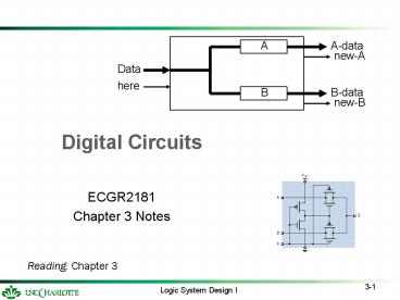
Digital Circuits
- ECGR2181
- Chapter 3 Notes
Reading Chapter 3
2
What is a digital system?
It is a organized collection of digital elements
which is designed to perform specified operations
on a set of digital inputs and to generate a set
of digital responses.
A digital system can be as simple as a block of
combinational logic or as complex as a
microprocessor.
3
Characteristics of Digital Systems
What are the characteristics of a digital system?
- Coordinate and sequence its internal operations.
- Data processing and storage.
- Cooperate in transferring data to from itself.
- Sequences operations of external entities.
4
Overview of a digital system
Sequencing Processing Storage
5
Input Output Signals
Data
- Multi-bit values
- Single-bit decision-making / information
Control generally single-bit signals
- Sequencing operations of system
- Coordinating operations with external units
6
Introduction to Digital Systems
Nomenclature (Terms to know.)
Word A group of binary bits. Typically
represents some element of data. The number of
bits in a word is indeterminate unless specified.
Example 24-bit word
Byte An 8-bit word.
Nibble A 4-bit word.
7
Introduction to Digital Systems
Structure of digital systems system vs.
module
- A digital system can be created as a monolithic
structure.
- Complex systems often need to be partitioned
into some - number of subsystems -- modules
- For small systems which can be conveniently
designed - monolithically the terms system and module
may be - used interchangeably.
8
Introduction to Digital Systems
Single module system
9
Introduction to Digital Systems
Multiple module system
System
10
Examples of digital systems
- Data Selector Route input data to one of two
outputs.
- Data Converter Inputs a 32-bit data word and
outputs it as 4 bytes.
- Message Generator Outputs a fixed message when
a start command is received
- Communications Buffer Receives and stores a
block of data. When the block is
complete, it resends the - stored data.
- Microprocessor Does everything!
11
A first look at the design process
1. Understand the functional specification.
2. Create a block diagram from the external
viewpoint.
3. Fill in the major internal components.
4. Determine the sequence of operations which
must occur within the module
12
Data Selector
Route input data to one of two outputs.
Specification When a new data word arrives at
the input, the module inspects the state of the
most significant bit and routes the data to
output A if the bit is true and to B if the bit
is false. The last value sent to either output
is retained until replaced.
13
Data Converter
Inputs 32-bit data word and outputs it as 4 bytes.
Specification When a new data word arrives at
the input, the module accepts it and then outputs
the word as 4 bytes.
14
Message Generator
Outputs a fixed message when a start command is
received.
Specification When a start command is
received, the module retrieves the bytes of a
message stored in an internal ROM and outputs
them sequentially.
ROM Memory
15
Communications Buffer
Receives and stores a block of data. When the
block is complete, it resends the data.
Specification The module receives a series of
data bytes and stores them in an internal memory.
Intake of data stops when a byte of all 1s is
received. Then it resends the message with pairs
of bytes packed in 16-bit words.
RAM Memory
16
Digital Logic
- Binary system -- 0 1, LOW HIGH, negated and
asserted. - Basic building blocks -- AND, OR, NOT
17
NAND and NOR
18
Truth Tables
F
X Y Z
XY X Y XYZ
19
More Practice
F
X Y Z
20
Many representations of digital logic
- Transistor-levelcircuit diagrams
21
-
Truth tables - Logic diagrams
22
Logic levels
- Switching threshold varies with voltage, temp,
process, etc. - need noise margin
- Operating closer to the tolerances requires an
increase in attention to analog behavior. - Logic voltage levels decreasing with process
- 5 -gt 3.3 -gt 2.5 -gt 1.8 V
23
MOS Transistors
Voltage-controlled resistance
PMOS
NMOS
24
CMOS Inverter
25
Alternate transistor symbols
26
Switch model
27
CMOS NAND Gates
- Use 2n transistors for n-input gate
28
- CMOS NAND -- switch model
29
CMOS NAND -- more inputs (3)
30
CMOS NOR Gates
- Like NAND -- 2n transistors for n-input gate
31
Make a 3-input NOR
32
NAND vs. NOR
- PMOS transistors have higher on resistance than
NMOS transistors.
Result NAND gates are preferred in CMOS.
33
Additional Terms
- Sinking/Sourcing Current (sect. 3.5.2, p. 106)
current entering/leaving the output of a device. - Fanout (sect. 3.5.4) how many gate inputs can a
particular device drive and still maintain
digital logic characteristics. - Unused Inputs (sect. 3.5.6) always connect
unused inputs to either power supply rail (Vcc or
Gnd.) - Static conditions may appear to be stable,
- Dynamic conditions could be unstable
- Makes circuit behavior unpredictable.
- ESD Electro-Static Discharge. (sect. 3.5.7)
ESD involves the discharge of static electricity
and is the deadly enemy of electronic circuits,
especially, CMOS devices. ESD damage can be
avoided with the use of ESD straps and rubber
mats. - Transition Time (sect. 3.6.1) time required for
signal to transit the abnormal region. The time
to transit the abnormal region may be different
for traversing the region in different directions.
34
More Terms
- Propagation Delay (sect. 3.6.2) time required
for a change on the input to produce a change on
the output. - Current Spikes (sect. 3.6.4) typically seen on
the power rails. Produced when many outputs
change at the same time. Switching Power
Supplies often produce these effects. t/s note
check frequency to help find source - Decoupling Capacitors (sect. 3.6.4) distributes
the filtering on the board and aids in the
reduction of noise on the power rails. - Ground Bounce (sect. 3.6.6) read the text.
describe how it looks on an oscope - Three-state Outputs (sect. 3.7.3) devices whose
outputs are one of three states, high, low and
high impedance. Used to drive an output from
multiple, mutually exclusive sources (or
devices.) - Different types of Logic Families
- TTL Transitor-Transitor Logic
- CMOS Complementary Metal Oxide Semiconductor
- ECL Emitter-Coupled Logic
- Take extreme care when interfacing TTL and CMOS
logic devices
Recommended
