
Torque on a Current Loop PowerPoint PPT Presentation
1 / 19
Title: Torque on a Current Loop
1
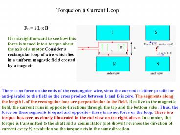
Torque on a Current Loop
FB i L x B
S
S
It is straightforward to see how this force is
turned into a torque about the axis of a motor.
Consider a rectangular loop of wire which lies in
a uniform magnetic field created by a magnet
N
N
There is no force on the ends of the rectangular
wire, since the current is either parallel or
anti-parallel to the field so the cross product
between L and B is zero. The segments along the
length L of the rectangular loop are
perpendicular to the field. Relative to the
magnetic field, the current runs in opposite
directions through the top and the bottom sides.
Thus, the force on these segments is equal and
opposite - there is no net force on the loop.
There is a torque, however, as clearly
illustrated in the end view on the right above.
In a motor, this torque is transmitted to the
shaft and a commutator (not shown) reverses the
direction of current every ½ revolution so the
torque acts in the same direction.
2
Torque on a Current Loop
This shows a rectangular loop of side length of a
and b, carrying a current I and immersed in a
uniform magnetic field B (into the page). The
long sides of the loop is labeled 1 3 and
short sides 2 4. In this orientation, the
magnetic force is outward from the center of the
loop.
The normal vector n perpendicular to the plane
of the loop defines the orientation of the loop
in the magnet field, but this only defines an
axis not a direction. Using the right hand rule,
curl the fingers of your right hand in the
direction of the current in the loop and your
thumb should point in the direction of the normal
vector n.
3
Torque on a Current Loop
The normal vector n of the loop is at an angle ?
to the direction of the magnetic field B. We want
to find the net force and net torque acting on
the loop in this orientation.
FB i L x B Force on a wire
The net force is the vector sum of the forces
acting on each side of the loop. For side 2 the
vector L points in the direction of the current
and has a magnitude b. The angle between L and B
for side 2 is 90o- ?. This the magnitude of the
force acting on this side is
Since the vector L is equal in magnitude, but in
opposite direction for side 4, F2 and F4 force
vectors cancel and the line action is through the
center of the loop so the torque contribution
from the forces on side 2 and side 4 is zero.
4
Torque on a Current Loop
The situation is different for sides 1 3. Like
sides 2 4, the forces exactly cancel each
other, however theses forces do NOT share the
same line of action so in this case they do
produce a net torque. The torque tends to align
the normal vector n with direction of the
magnetic field B. The torque has moment arm
(b/2) sin? about the center of the loop. The
magnitude ? of the torque due to forces F1 and
F3 is
? r x FB (b/2) sin? FB where FB
iaB
5
Torque on a Current Loop
If we replace the single loop of current with a
coil of N loops or turns that are tightly
wounded, they can be approximated as having the
same dimensions and lying in a plane. Then the
turns form a flat coil and the torque ? for a
single loop acts on each loop in this coil. Then
the total torque is
In which Aab the area enclosed by the coil. The
quantities (NiA) are grouped together since they
are properties of the coil . This value (NiA) is
referred as the magnetic moment ?. The above
relationship can be generalize in vector form as
6
Calculating the magnetic Field Due to a current
Recall that one way to produce a magnetic field
is with an electric current and given a
distribution of currents, the resulting magnetic
field can be calculated. The same procedure used
to calculate the electric field from distribution
of charges will be applied. Recalling that we
first mentally divided the charge distribution
into elements dq, as done for the charge
distribution in the figure, and then calculate
the field dE produced by the charge element dq at
some point P. Due to superposition, we
calculate the total net field E at P by summing
or integrating the contributions dE from all the
elements. dE is in the direction of r, where r is
the vector between charge element dq and P. The
above equation can be re-written in vector form
as
Vector r, NOT an unit vector
Since the magnitude of r is in the numerator, the
exponent on r in denominator is now 3
7
Calculating the Magnetic Field Due to a current
This procedure will be used to determine the
resulting magnetic field from a current. The
figure shows an arbitrary shaped wire carrying a
current i and we want to determine B field at
point P. We mentally divide the wire into
differential vector segments ds that have a
magnitude of length ds and a direction that is
tangent to wire and in the direction of the
current i.
We define a differential current-length element
to be i ds and we want to calculate the field dB
at P by this current length element.
Like electric fields, magnetic fields can be
superimposed to determine a net field so the net
field B at P can be calculated by summing or
integrating the contributions dB from all the
current length elements.
This summation is more challenging than the
process with electric fields, since a charge
element dq is a scalar while a current-length
element i ds is a vector
8
Calculating the Magnetic Field Due to a current
The magnitude of dB produced at point P by a
current-length element i ds has been determined
to be
where
called the permeability constant
The vector form of this relationship is
The vector and scalar form of this relationship
is called the law of Biot-Savart Law
9
Magnetic Field due to a Current in a Long
Straight Wire
We want to determine the B field at point P from
the current i in a wire that is straight and
infinite length.
The magnitude of the differential magnetic field
produced at P by the current-length element i ds
located a distance r from P is given as
The direction of dB is that of ds x r, directly
into the page.
dB at point P has this same direction of all the
current-length elements on the wire.
We can find the magnitude of the magnetic field
produced at P by the current-length elements in
the upper half of the upper half by integrating
dB from 0 to ?.
A current length segment in the lower half that
is as far below P as ds is above P produces
magnetic field of the same direction and
magnitude.
We need only to multiply the result of the
integral by 2 to find the total magnetic field
10
Magnetic Field due to a Current in a Long
Straight Wire
Therefore the resulting integral is
?, s and r are not independent of each other and
are related by
Making these substitution, we find that
11
Magnetic Field due to a Current in a Long
Straight Wire
The field magnitude depends only on the current
and the perpendicular distance
The field lines of B form concentric circles
around the wire as shown below.
The increase in spacing of the lines wrt
increasing distance from the wire represents the
1/r decrease in magnitude
12
Magnetic Field due to a Current in a Long
Straight Wire
A simple right hand rule for finding the
direction of the magnetic field set up by a
current-length element
13
Magnetic Field Due to a Current in a Circular Arc
of Wire
Finding the magnetic field at a point by a
current in a curve wire, we would again use
Biot-Svart Law
to write the magnitude of the field produced by a
single current-length element and we would again
integrate to find the total field by all elements.
This integration can be difficult, depending on
the shape, but when the wire is circular arc and
the point is at the center of curvature, it is
quite simple.
14
Magnetic Field Due to a Current in a Circular Arc
of Wire
The left figure shows such an arc-shape wire with
central arc angle ?, radius R and center C,
carrying current i. At C, each current-length
element i ds of the wire produces a magnetic
field dB as given by
The left figure shows, that no matter where the
element is located on the wire, the angle ?
between the vectors r and ds is 90o and r R
15
Magnetic Field Due to a Current in a Circular Arc
of Wire
By substituting R for r and 90o for ?, we obtain
from
We get the follow integral
Integrating we get the following result
This equation gives the field only at the center
of the arc and ? is in radians
16
Sample problem
The wire in the figure carries a current I and
consist of a circular arc of radius R and central
?/2 radians and two straight sections whose
extensions intersect the center C of the arc.
What is the magnetic field at C ?
We can apply the Biot-Savert Law separately into
3 sections
(1) left straight section (2) right straight
section (3) circular arc
17
Sample problem
For any current-length element in section (1),
the angle ? between ds and r is zero, therefore
Thus the current along the entire wire in
straight section (1) contributes no magnetic
field at point C.
The same situation occurs in straight section
(2), where the angle ? between ds and r for any
current-length element is 180o. Therefore,
18
Sample problem
Since the curve section (3) is a circular arc and
we are to find the magnetic field at the center
of curvature, we can use the result derived
earlier
Recalling that this arc has a radius of R and ?/2
radians By substituting ?/2 for ? and R for R, we
have
By applying the right hand rule as shown to the
right, we see that B3 points into the page at
point C.
Therefore the total magnetic field B at point C
has the magnitude
Into the page
19
Check Quiz
Recommended
