
HA3SR.58 Design and Construction PowerPoint PPT Presentation
1 / 29
Title: HA3SR.58 Design and Construction
1
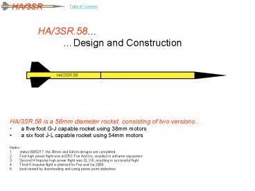
HA/3SR.58 Design and Construction
HA/3SR.58
- HA/3SR.58 is a 58mm diameter rocket, consisting
of two versions - a five foot G-J capable rocket using 38mm motors
- a six foot J-L capable rocket using 54mm motors
- Notes
- status 06/02/17 the 38mm and 54mm designs are
completed. - First high power flight was at ERC Fire And Ice,
resulted in airframe separation - Second H Impulse high power flight was SL XIII,
resulting in successful flight - Third H Impulse flight is planned for Fire and
Ice 2006. - best viewed by downloading and using power point
slideshow
2
Table of Contents
This slide package is divided into three
sections Design, Construction, and Assembly.The
design part talks about what is being built.
The construction part is about how it was
built.The assembly section helps to explain how
the rocket is assembled once construction is
completed. Ie. at the launch site.
- 1. Design
- Design Summary
- Scale Drawing 38mm
- Scale Drawing 54mm
- Major Components
- Fin Can 38mm
- Fin Can 54mm
- Avionics/Recovery
- Nose Cone
- Fin Dimensioning
- Avionics Bay pyro control block diagram
- Avionics Bay switching, arming, and indicators
- Mass Estimate
- Recovery
- Shear pins
- Ejection Charge Sizing
- 2. Construction
- Construction Summary
- Lower Airframe
- motor mount assembly
- motor mount attachment to airframe
- Motor retainment
- Avionics/Recovery Airframe
- avionics layout
- Avionics/Recovery Assembly
- Nose Cone
- harness attachment
- 3. Assembly and Flight Profile
- tab a into slot b
- a pictorial
- flight profile
3
Design Summary
- Overall Design
- 6 feet high, 58 millimeter diameter, dual
deployment - 3 sections Fin Can, Avionics/Recovery, Nose Cone
- capable of 1-6 grain 38mm casings
- Flight Profile 38mm (from wRASP, for CTI J330,
1385gm dry, standard day) - maximum expected altitude 7541.8ft
- Time to maximum altitude 19.07s
- maximum expected acceleration 21.53G
- maximum expected velocity 715.0ft/s, Mach 0.95
- velocity as the rocket leaves the launch rail
60.5mph (6ft rail) - Flight Profile 54mm (from wRASP, for CTI L730-P,
1385gm dry (tbd), standard day) - maximum expected altitude 18692.2ft
- Time to maximum altitude 27.186s
- maximum expected acceleration 32.51G
- maximum expected velocity 1457.3ft/s, Mach 1.94
- velocity as the rocket leaves the launch rail
74.0 mph (6ft rail) - Recovery
- drogue deployment controlled by on board dual
electronics - main deployment controlled by on board dual
electronics at low altitude
4
Design Scale Drawing for 38mm motor mount version
47.96
3 fins, see Fin Dimensioning slide
45.68 CG max
40 CG 6 grain
CP 3.5 Caliber CG ? ?
G-Wiz
Harness
Parachute
Harness
Motor Mount
DB
DB
36
10
15
61
- Notes
- Outside diameter of airframe is 58mm
- CP calculated using Barrowman Equations
- CG based on CTI J330
5
Design Scale Drawing for 54mm motor mount version
59.31
3 fins, see Fin Dimensioning slide
52 CG
CP 2.55 CG Caliber ? ?
G-WIZ
Harness
Parachute
Harness
36
9.5
29.5
75
- Notes
- Outside diameter of airframe is 58mm
- CP calculated using Barrowman Equations
- CG based on CTI L730-P
- Fin can is minimum diameter design, sized for
Cesaroni P54-6GXL casing
6
Design Major Components
- Fin Can
- 22 overall, with 3x 6mm 5ply plywood fins- 16
motor mount- 6 for lower harness - 2 coupler for insertion into airframe
- Capable of Cesaroni 1 to 6 Grain 38mm casings
- For 54mm motors, the fin can is 36 overall
- Also does not contain motor mount tube
- Avionics/Recovery Airframe
- 28 overall- 2 reserved for lower coupler- 6
avionics bay- 2 for wadding (DB)- 6 for upper
harness- 10 for main chute- 2 reserved for
nose cone shoulder - Nose Cone
- 9.5 54mm ogive cone
- Avionics Bay
- 6 54mm CT, contains G-Wiz flight computer
- mounts inside avionics/recovery airframe
Harness
Motor Mount
22
G-Wiz
Harness
Parachute
DB
DB
28
9 1/2
G-Wiz
7
Design Fin Can 38mm motor mount
- 5/16 Closed Eyebolt
- Forward Rail Button
- Coupler
Motor Mount
22
- Fin Can design considerations
- 22 overall
- 3x 6x3 6mm plywood fins (see Fin Dimensioning
slide for more details on fins) - contains 16 38mm motor mount tube, centered
using 2x 5mm centering rings - designed specifically for Cesaroni 1-6 grain
casings - Slim Line motor retention
- Closed eyebolt to anchor harness
- 2 coupler section used for insertion into
electronics airframe - Two Delrin 1000 rail buttons screwed and CAd
into airframe
8
Design Fin Can 54mm minimum diameter
Cesaroni P54-6GXL Casing
20.5
26.5
36
- Fin Can design considerations
- 36 overall
- 3x 6x3 1/8 plywood fins (see Fin Dimensioning
slide for more details on fins) - Fins are surface mounted to airframe
- designed specifically for Cesaroni P54-6GXL
casing, but can accept any Cesaroni 54mm motor - Slim Line motor retention
- Closed eyebolt to anchor harness
- 2 coupler section used for insertion into
electronics airframe - Two Delrin 1000 rail buttons screwed and CAd
into airframe
9
Design Avionics/Recovery
Dog Barf
Dog Barf
NC Shoulder
Electronics
Upper Harness
Parachute
Lower Harness
6
2
2
6
10
2
28
- Avionics/Recovery design considerations
- 28 BT section provides strength, rigidity, and
protection to electronics bay - Lower portion of BT contains electronics bay
- Upper portion of BT contains upper recovery
harness and parachute - Harness is a modified through the bay design,
with harness actually passing on the outside of
the bay - Lower harness is shown for clarity when rocket
is assembled harness is inserted into the upper
fin can - 6 CT Electronics Bay inserted into BT section up
to internal collar, then secured using three
4-40 bolts - Parachute is 3 Giant Leap
10
Design Nose Cone
- Forward Bulkhead assembly, integrated into
nosecone shoulder - Made of
Nose Cone
2
9.5
- Nose Cone design considerations
- Forward bulkhead (a washer) is integrated into
nose cone coupler - Upper harness is fed through washer and knotted,
then inserted into nose cone - Ogive NC provides aerodynamic efficiency
- Note that future designs will attempt to
integrate GPS positional awareness into nose cone
11
Design Fin Dimensioning
Fin Dims (for Barrowman Calculations) Root
cord 6 Tip cord 1.5 Semi span 3 Mid
cord 3.5 Material 5 ply 6mm plywood
1.5
0.5
3.0
7.5mm
Through the wall fin tab
6.0
- Notes
- For the minimum diameter design, there is no fin
tab - Minimum diameter version uses 1/8 plywood
12
Design Electronics Baypyro control block
diagramrework to G-WIZ design
MAIN PYROs ARM
J1-1 J1-2 J1-3 J1-4 J1-5 J1-6
POWER Breakwire (shorted) Ext. Pyro enable
(n/c)
AFC-877
J2-1 -J2-2
9V n/c
Onboard 9V
DROGUE PYROs ARM
J5-1 J5-2 J5-3 J5-4 J5-5
13
Design Electronics Bayswitching, arming, and
indicatorsrework to G-WIZ design
- Pyro Notes
- Easy access to enable pyro electronics at the
launch rail - Switches are switched to the right for ON or
ARM - When pyro switches are not armed, charges are
shorted by pyro switch - Switches mounted to electronics pallet
- CT slides over pallet, small holes in BT/CT give
access to switches
AFC-877 Flight Computer
PYRO Drogue
PYRO Main
POWER
14
Design Mass Estimate
- As the construction proceeds, will continue to
re-estimate - Lower Airframe (less motor and casing) 480
- Electronics (can be optional) 270
- Upper airframe (including harness, parachute) 635
- (Margin, to account for epoxy, paint, and misc) 0
- Total 1385 gm
- Note that the design mass excluding motor cannot
exceed 1293gm to be considered a model (1293
207 for G79 1500gm) - Turn out the mass is 92gm over, therefore not a
model. Need to explore opportunities to reduce
the mass if the rocket is to be flown as a model
15
Design Recovery
- Recovery design considerations
- High speed recovery based on lower harness
serving as drogue, therefore 100ft/s - Parasheet size based on a 1.995kg rocket, less
0.392kg for spent propellant, therefore 1.603kg - Based on 1.6kg, the chosen main chute is then 3ft
- 3ft chute provides low speed recovery fall rate
of 24-30ft/s (from rocket calc) depending upon
motor - Main deployment planned at 1200-1500ft AGL for
H-J motors, 800ft for G motors - Sample AFC programming is highlighted in the
spreadsheets below - Harness design considerations
- recovery harness is a one piece 60ft length of
half inch tubular nylon - harness is attached at one end to eye bolt
mounted to baffle in the fin can - Other end is attached to a washer inserted into a
slot in the nose cone - parachute is attached to the upper part of
harness using 1000lb swivel - Harness is fixed to the middle of the
recovery/avionics airframe at the electronics bay
16
Flight Profile
Pre-launch and ascent
Hyper speed descent
High speed descent
Low speed descent
17
Design Shear pins
- Shear pins are used to keep the airframes
together during the flight. - There are two sets of shear pins (which are
actually nylon screws)... - The lower set keeps the lower airframe attached
to the upper airframe during ascent until apogee - The upper set keeps the nose cone attached to
the upper airframe during high speed descent - Design considerations
- both sets of shear pins must be strong enough to
survive the drag forces that will tend to
separate the sections - the lower set must give way to the ejection
charge forces that separate the sections for high
speed descent - in the meantime, the upper set must survive the
forces that separate the sections in 2. - the upper set must give way to the ejection
charge forces that separate the sections for low
speed descent - Achieving 1 and 4 are easy, choose a size and
number that are large enough to meet 1/3, but
small enough to meet 2/4. - Achieving 2 and 3 are a little more challenging
the drogue ejection force must be strong enough
to meet design consideration 2, while at the same
time weak enough to meet design consideration 3.
18
Design Ejection Charge Sizing
8
18
- Choosing the amount of blackpowder
- Drogue charge sizing
- based on a 54mm diameter tube, 8 inches long
0.41gm in other words 0.5gm. - seems small, but Im used to larger airframes
- provides 100lbf, at 28PSI
- Ejection charge test results based on LDRS24
ejection charge testing, and successful
deployment at Sullivan Lake XIII, 1.75gm for
drogue. - Main charge sizing
- based on a 54mm diameter tube, 18 inches long
0.93gm in other words 1.0gm - still seems small provides 100lbf, at 28PSI
- Ejection charge test results based on LDRS24
ejection charge testing, and successful
deployment at Sullivan Lake XIII, 2.0gm for
drogue.
19
Construction Summary
- Lower Airframe
- three fins initially epoxied to motor tube,
filleted, then glassed 1x - two centering rings on motor tube, one at rear of
fin, one at fore - outer airframe slides over motor tube assembly,
epoxied, then glassed 2x - 54mm minimum diameter does not use motor mount
- Avionics Bay
- contains electronics pallet secured in place with
inner/outer bulkheads - pallet contains pyro control and externally
accessible switches - Secured to inside of avionics/recovery airframe
using three 4-40 bolts - Avionics/Recovery Airframe
- contains internal collar to fix avionics bay into
place - secured to lower airframe with two 2-56 nylon
shear pins - nose cone secured to upper airframe using two
2-56 nylon bolts
20
Construction Lower AirframeFin attachment and
centering ring attachment, to motor mount tube
- 36mm mm tube
- 2x centering rings
- 3x fins
- 38mmm motor mount version
- Fin tabs epoxyd to motor mount
- 1 layer 4oz fiber glass, laid across motor mount
tube and extending approximately 1 towards fin
tips, then epoxied, to form strong fillet - applied to all three fin faces and trimmed to
size - the three fins, the motor mount tube, and the two
centering rings all become one epoxied together
assembly - further glassing applied tip to tip across
airframe, once motor mount is fitted into lower
airframe (next slide) - 54mm minimum diameter version
- Similar process, 1st layer for fillet buildup,
2nd layer for fin stabilation, 3rd layer tip to
tip for rigidity
- 54mm airframe
- 6x fin fillet buildup
- 3x fin stabilization
21
Construction Lower Airframe38mm Motor Mount Fin
Assembly attachment to airframe
- Lower airframe, with slots in the airframe for
the fins, is slid over motor mount tube assembly
and epoxied into place - 38mm design has 2nd layer of fiber glass applied
across airframe and fins from tip to tip - 54mm design has1st layer of glass applied to fin
fillets2nd layer of glass partway out to fin
tips,3rd layer tip to tip
22
Construction Motor retainment, rail buttons, and
aft harness attachment
- Aft rail button, screwed into and CAd to
airframe - Slimline Motor Retainer, JB Welded to motor mount
tube, or aiframe for 54mm minimum diameter
- Notes
- Motor is retained using slimline retainer
- Eyebolt/baffle assembly is secured against
coupler - Fore rail button mounted at the CG, for a 6 grain
casing - 54mm design eliminates motor mount, and uses 54mm
retainer
23
Construction Avionics Bayconstruction /
assembly,and physical layout
Side View
FC-877 v1.1a Launch Wait
- Notes
- Switches are externally accessible
- LEDs are externally visible
Top View
FC-877 v1.1a Launch Wait
Bottom View
6
24
Construction Avionics/Recovery Airframeassembly
of electronics bay into electronics airframe
Avionics Bay
- Avionics Bay butts up against secure internal
collar - One set of three 4-40 bolts
- Notes
Avionics Bay
25
Construction Nose ConeHarness Attachment
- Notes
- Harness is fed through washer
- Two knots are tied in harness
- Washer/knot assembly is pushed through nose cone
shoulder coin slot - Washer cannot pull out without manipulating it
into the right orientation - On nose cone ejection, unlikely for washer to be
in correct orientation
- Two 2-56 nylon shear pins
- Coin Style slot
- Oversize washer
- Bulky knot (bigger than washer hole)
- Assembly is knotted again on outside of nose cone
to fix its location
(part of) tubular nylon harness
26
Checklists Before Flight Day Prepatory tasks
- Prepare CAR Flight Data Sheet
- Prepare CAR Rocket Inspector Pre-Flight
Inspection Checklist - Build ejection charges Pyro 1 ____ gm, Pyro 2
____ gm, Pyro 3 ____ gm - Program pyro 1 Cluster/Stage NA, single motor
only - Program pyro 2 Apogee 0s
- Program pyro 3 Main 800ft
- Shunt the pyro connector
- Connect pyros cluster N/C, 1.75gm on drogue,
2.00gm on main - Turn on pryo and FC batteries no alarm beeps,
one cluster beep, two drogue beeps, two main
beeps - Turn off FC Battery, pryo battery, remove pyro
shunt for assembly - Assemble avionics bay
- Insert pyro shunt
27
Assembly a pictorial
Electronics Bay
Avionics/Recovery Airframe
Harness
28
Checklists Flight Day Rocket Assembly Tasks,
and Final Checklist
- Rocket Assembly Tasks
- Integrate avionics bay and airframe, insert shunt
- DO WARNING! Turn on FC, check for proper beeps,
turn off FC - Prepare main parachute and shrouds, loop upper
harness into parachute swivel at proper
attachment point - Insert majority of upper harness into upper part
of airframe - Insert packed and protected parachute into upper
airframe - Integrate nose cone and secure using two 2-56
shear pins - Stuff lower harness into lower part of airframe
- Integrate fin can into aft end of
avionics/recovery airframe - Secure fin can and airframe using two 2-56 nylon
shear pins - Assemble motor according to manufacturer
instructions - Place motor into lower airframe, secure using
Slimline retainer - DO WARNING! Turn on AFC, listen for continuity on
the pyros - turn off AFC
- Put electronics Switch Tool in pocket
- Get the flight data sheet, RI Checklist, go
to launch table
- Final Checklist
- Give flight data sheet to RI / LCO, and await
inspection - Go to the assigned launch rail
- Mount rocket on the rail
- Get a picture, a video
- DO WARNING!
- Turn on the pyro battery, then FC battery
- listen for continuities
- remove shunt, double check continuities
- Connect igniter to firing system and check
continuity, disconnect - Insert igniter, tape into place. Secure wiring to
launch pad - Reconnect igniter, check continuities once more
- Pray to the rocket gods, then return to launch
table
29
Checklists Flight Day Miscellaneous Checklists
Failed Launch Checklist On range open, go to
rocket and disconnect igniter from the firing
system Remove the igniter from the motor Shunt
the pyros Turn off the flight computer Inspect
problem, in anticipation of another attempt to
launch In Flight Operations Watch in awe with
videocam in hand Attempt to observe drogue
ejection Attempt to observe main ejection Attempt
to observe landing location, line up with a
couple landmarks Go for a walk to retrieve
rocket Recovery Checklist If not proper
deployment, shunt pyros Listen for
altitude Partially re-assemble rocket and return
to launch area Disassemble rocket and download FC
data into laptop for further analysis
Recommended
