
Ethernet Cables PowerPoint PPT Presentation
1 / 47
Title: Ethernet Cables
1
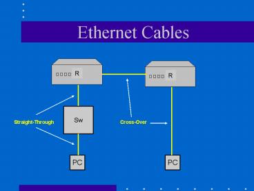
Ethernet Cables
R
R
Sw
Straight-Through
Cross-Over
PC
PC
2
Twisted-Pair Cabling
- Common traits of all twisted-pair cabling types
and categories - The wires are copper
- The wires come in pairs
- The pairs of wires are twisted around each other
- The pairs of wires are usually enclosed in a
cable sheath individually and as a group of wires
3
Twisted-Pair Cabling
- Crosstalk
- Signal bleed from one cable to another
- Usually occurs in poorly wired media
- Cancellation
- Insulates the signal from the effects of signal
bleeding
4
Unshielded Twisted-Pair (UTP)
- Cabling used for a variety of electronic
communications
CAT 5e Designed to correct shortcomings of CAT
5, particularly for Gigabit Ethernet and
full-duplex operation. Signaling rate 100MHz
like CAT 5. CAT 6 Recommended cabling for
Ethernet over copper at speeds up to 1 Gigabit.
Signaling rate up to 200MHz.
5
Unshielded Twisted-Pair (UTP)
- UTP advantages
- Thin flexible cable that is easy to string
between walls - Most modern buildings come with CAT 5e or CAT 6
UTP already wired into the wall outlets or at
least run between the floors - Because UTP is small, it does not quickly fill up
wiring ducts - Costs less per foot than other type of LAN cable
6
Unshielded Twisted-Pair (UTP)
- UTP disadvantages
- Somewhat susceptible to interference
- Pair twisting does help, but it does not make the
cable impervious to electrical noise - Its unrepeated length limit is 100 meters
7
RJ-45 Connectors
- Registered Jacks (RJ)
- Type of telecommunication connector used for
twisted-pair cabling - Typically RJ-45 connectors resemble the typical
RJ-11 connectors that connect the phone to the
wall - Difference between RJ-45 connectors and RJ-11
connectors is that the former has eight wires
(four-pair) and the latter four (two-pair) - Some RJ-11 connectors are used with three-pair
(six-wire) UTP
8
Terminology
- The RJ-45 jack is the receptacle
- And the RJ-45 plug is the connector at the end of
the patch cable
9
Horizontal Cabling Standards
- Horizontal cabling
- The twisted-pair or fiber-optic media connecting
workstations and wiring closets - Electronics Industries Alliance and
Telecommunications Industry Association (EIA/TIA) - Define a set of specifications which covers
outlets near the workstation, mechanical
terminations in wiring closets, and all cable
running along the horizontal path between wiring
closet and workstation (EIA/TIA 568A cabling
standards, EIA/TIA 569 pathways and spaces)
10
Horizontal Cabling Standards
11
Horizontal Cabling Standards
- EIA/TIA-568A
- Specifies that the maximum distance for a UTP
horizontal cable run is 90 meters (295 feet) - Total of 10 meters is allowed for patch cables
(a.k.a. patch cords) - In addition to UTP, the following cable types may
be used for horizontal pathways - STP Shielded Twisted Pair
- Fiber-optic
12
Wiring Closets
- Contain the wiring and wiring equipment for
connecting network devices, such as routers,
switches, patch panels, and hubs - EIA/TIA-568 and EIA/TIA-569 standards apply to
the physical layout of media and wiring closets,
with the latter stating there must be a minimum
of one wiring closet per floor - Furthermore, when a given floor area (catchment
area) exceeds 1,000 square meters, or the
horizontal cabling more than 90 meters,
additional wiring closets are needed
13
Wiring Closets
- The main distribution facility (MDF) is the
central junction point for wiring of a star
topology - The additional closets are called intermediate
distribution facilities (IDFs) - IDFs are required when
- Catchment area of MDF is not large enough to
capture all nodes - The LAN is in a multistory facility
- The LAN encompasses multiple buildings
14
Proximity to the POP
- Ensure that main wiring closet is close to the
point of presence (POP) to a wider network, e.g.,
to the Internet.
Network spanning multiple buildings
15
Proximity to the POP
Network spanning multiple floors
16
Backbone
- Backbone cable (sometimes called vertical
cabling) connects wiring closets to each other in
an extended star topology - EIA/TIA-568A specifies four different options for
backbone cabling - 100-ohm UTP
- 150-ohm STP
- 62.5/125-micron optical fiber (multi-mode)
- Single-mode optical fiber
17
Installing Connectors
RJ-45 connector
18
Installing Connectors
UTP wires
19
Installing Connectors
Jack wiring (T568B)
20
Installing Connectors
- EIA/TIA-T568B
- Wiring method used to indicate which colors are
assigned to which pin for UTP cable - T568A is sometimes used (different color
termination sequence) - Punch tool
- Used to punch down cable at the patch panel or
wall plate - Crimp tool
- Used to terminate RJ-45 plug on cable
21
Patch Panel
Patch panel (back) pins
22
Patch Panel Punch Tool
Patch panel ports
Punch tool used to terminate horizontal cable at
back of patch panel
23
Crimp Tool
Used to attach plug to patch cable
24
Color Scheme
- Association of pair number with color
- Originally used by the telephone industry
- Pair 1 - White with blue strips (W-Bl)
- Blue with white strips (Bl)
- Pair 2 - White with orange strips (W-O)
- Orange with white strips (O)
- Pair 3 - White with green strips (W-G)
- Green with white strips (G)
- Pair 4 - White with brown strips (W-Br)
- Brown with white strips (Br)
25
Termination Sequence
- EIA/TIA
- T568B termination standard
- Most widely used for data communication
- Defines the order in which incoming pairs are
terminated into plug pins
26
T568B Standard
- Each end wired the same, i.e., straight through
- Plug receptacle end with locking tab at bottom
- Yellow pairs/pins used for 10BaseT 100BaseT
27
Cross-Over Cable
- Also called an uplink cable
- Cross transmit and receive at one end
- That is, use T568A at one end T568B at other
28
Cross-Over Cable
29
Straight-Through Cross-Over
Standard Cross-Over
30
Pin Numbers
Locking tab on back
31
Making Patch Cable
- Cut a about 1½ to 2 of cable off the roll, or
cut the plugs off an old cable. - Cut about 2 of the jacket from the end.
- Cut away the ripcord and discard it.
- Untwist the pairs and arrange them in the T568B
color sequence. - Cut all eight wires squarely ½
- from the jacket with the wire
- cutter.
32
Making Patch Cable
All the way to end
- Insert wires into the plug and push them all the
way to the end. - Insert the plug into the crimping tool. Press
the handles together firmly. Remove plug from
tool.
33
Making Patch Cable
- Inspect plug to be sure the termination is
correct - Conductors should all be touching the end of the
plug. - All 8 pins should be fully depressed.
- The pins feet should be fully inserted into the
wire. - The flange should be fully
- depressed against the jacket,
- and the end of the jacket should
- be beyond the flange.
34
Cable Testers Wire Map
- Important measurement a cable tester makes to
check wiring sequence
Wire map error detection
35
Cable Testers Wire Map
Crossed pairs
Split pairs
36
Cable Testers Attenuation
- Attenuation is the loss of signal power over the
distance of a cable - Signal injector
- Puts traffic on a wire so that a cable tester can
measure attenuation and crosstalk - The lower the attenuation, the better
37
Cable Testers Noise
- Alternating current (AC) signal noises are called
oscillations and can alter the digital signals
that computers receive on the wire - The motherboard and other internal integrated
circuits of a computer use the chassis as their
ground - Faulty AC wiring can also cause problems with
transmissions because the signal reference ground
is the computer chassis and grounding plate
38
Cable Testers NEXT
- Near end crosstalk (NEXT)
- Measure of interference from other wire pairs
- Causes of NEXT include
- Split pairs
- Too much wire untwisted at the patch panel, jack,
or connectors - Bends, kinks, or stretches in the cabling
39
Cable Testers NEXT
NEXT test on a cable analyzer
40
Cable Testers Distance Measure
- EIA/TIA-568A specifies maximum cable lengths for
network media - Cables that are too long can cause delays in
transmission and network errors - Time-domain reflectometer (TDR)
- Cable tester that can detect the overall length
of a cable or the distance to a cable break
41
Three-Layer Network Model
- Divides a network into three connectivity layers
- Consists of
- Core layer
- WAN technology to interconnect sites
- Forms the higher-level backbone
- Distribution layer
- Backbone network used to interconnect buildings
- Forms the campus network
- Access layer
- LAN or group of LANs providing connectivity for
end-stations (servers, workstations, printers) - Technology closest to users
42
Three-Layer Network Model
Three-layer hierarchical network model
43
Two One-Layer Network Models
- Two-layer network model
- Divides a network into two connectivity layers
- Core
- Access
- One-layer network model
- Smaller networks
- Includes WAN connectivity equipment and LAN
connectivity equipment in same layer - May be adapted to the two-layer and three-layer
design models in the future - Note that the difference between the three models
is the number of levels of routers
44
Two-Layer Network Model
Two-layer hierarchical network model
45
One-Layer Network Model
One-layer network model
46
Summary
- UTP cabling
- Nomenclature EIA/TIA, wiring closet, MDF, IDF,
POP, horizontal cable, vertical (backbone) cable - Installing connectors
- Cable testers
- Network hierarchy models
47
End
Recommended
