
Crash Simulations Using LSDYNA PowerPoint PPT Presentation
1 / 19
Title: Crash Simulations Using LSDYNA
1
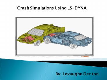
Crash Simulations Using LS-DYNA
Getty Images
By Levaughn Denton
2
Outline
- Background
- Ls-Dyna
- Front Rail Testing
- Project Design/Methods
- Front rail example
- Dodge Neon example
- Specific Aims
- Quadtree hierarchical structure
3
LS DYNA Software (Livermore Software Technology
Corp.)
- Solve multi-physics problems
- Thermal stress
- Load
- Use LS DYNA to determine the deformation of a
frontal rail (or bar) after impact - Using a single processor
- 2 processor implementation is possible
4
LS DYNA Options
- Several versions of LS DYNA
- Windows
- Parallel (memory can be allocated differently)
- Serial
- Unix
- Parallel
- Serial
- Linux
- Parallel
- Serial
- Each has its own set of keywords
5
Frontal Crash Simulation
- Frontal rails play an integral role in crash
tests - Responsible for absorbing energy during an impact
- Amount of energy absorbed is directly
proportional to a vehicles deformation
Getty Images
6
Crash Test Methodologies
- Quasi-Static Testing
- Frontal rail will experience deformation as a
result of a constant force
Getty Images
7
Crash Test Methodologies Contd
- Impact Testing
- Frontal rail will experience deformation as a
result of an initial impact speed that decreases
with time
Velocity at Time 2 lt Velocity at Time 1
8
Simulate a Frontal Rail
- Finite Element Model
- Split into planes of symmetry in bar
- Model only a portion of the bar
- Crash into a rigid wall
Getty Images
9
LS-DYNA Input Parameters
- Given the material parameters, a grid of nodes
will be generated - 1369 nodes
- Each node has an initial velocity in the z
direction
Material Model 1 Density (g/cm3) 8.98 Elastic
Modulus (g/microsec.2 cm) 1.1 Tangent Modulus
(g/microsec2 cm) 1.0x10⁻³ Yield Strength
g/microsec2 cm) 4.0x10⁻³ Harding Parameter 1.0
Getty Images
10
LS-DYNA Input File
- First block of code defines output parameters
- Units gm, cm, microsec, 1e07 N, Mbar, 1e07
N-cm
- Control Ouput
- ...gt....1....gt....2....gt....3....gt....4....gt....5
....gt....6....gt....7....gt....8 - CONTROL_TERMINATION
- endtim endcyc dtmin endneg
endmas - 82.10
- CONTROL_ENERGY
- hgen rwen slnten rylen
- 2
11
LS-DYNA Input File Contd
- Second block of code defines Mesh and Material
Parameters - Define Parts and Materials
- ...gt....1....gt....2....gt....3....gt....4....gt....5
....gt....6....gt....7....gt....8 - PART
- pid sid mid eosid
hgid adpopt - Bar
- 1 1 1
- MAT_PLASTIC_KINEMATIC
- mid ro e pr
sigy etan beta - 1 8.930 1.17 0.350
0.004 0.001 1.0 - src srp fs
- 0.0 0.0 0.0
Material Model 1 Density (g/cm3) 8.93 Elastic
Modulus (g/microsec.2 cm) 1.1 Tangent Modulus
(g/microsec2 cm) 1.0x10⁻³ Yield Strength
g/microsec2 cm) 4.0x10⁻³ Harding Parameter 1.0
12
LS-DYNA Input Parameters Contd
Getty Images
Third block of code defines boundary definitions
Initial Conditions ...gt....1....gt....2....
gt....3....gt....4....gt....5....gt....6....gt....7....
gt....8 Nodes within box 2 are given an
initial velocity in the neg z-direction.
These are all the nodes except for those on the
bottom of the bar. INITIAL_VELOCITY nsid
nsidex boxid 0 0
2 vx vy vz vxe
vye vze 0.0 0.0 -0.0227
0.0 0.0 0.0
13
LS-DYNA Input Parameters Contd
Getty Images
Third block of code defines boundary definitions
Define
Nodes and Elements
Many nodes have boundary conditions to
simulate symmetry. NODE node
x y
z tc rc 1
0.000000E00 0.000000E00 0.000000E00
7 7 2 5.330000E-02
0.000000E00 0.000000E00 5 7
3 1.067000E-01 0.000000E00
0.000000E00 5 7 4
1.600000E-01 0.000000E00 0.000000E00
5 7 5 2.133000E-01
0.000000E00 0.000000E00 5 7
14
Results After Impact
HP Pavilion dv2700 3GB RAM w/ (2 CPUs) Time
278 secs 1 CPU
15
Neon Crashed Into a Rigid Wall
http//www.topcrunch.org/benchmark_results.sfe
16
Improving the Performance(software approach)
- The mesh storage structure has a direct impact on
the - the amount of memory used
- the CPU time necessary for assembly
- the complexity of the programming
- Suggest the quadtree hierarchical structure is
used to store information
17
Quadtree Structure Contd
- Locate part of the frontal rail that experienced
deformation using the boundary coordinates of a
node
18
Quadtree Structure
LULEÅ UNIVERSITY OF TECHNOLOGY Department of
Computer Science and Electrical Engineering
With a depth, d, a neighboring node can be found
in O(d 1) time.
19
Thank You
Recommended
