
System Development PowerPoint PPT Presentation
Title: System Development
1
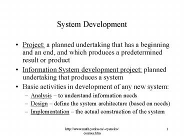
System Development
- Project a planned undertaking that has a
beginning and an end, and which produces a
predetermined result or product - Information System development project planned
undertaking that produces a system - Basic activities in development of any new
system - Analysis to understand information needs
- Design define the system architecture (based on
needs) - Implementation the actual construction of the
system
2
System Development Life Cycle (SDLC)
- The systems development life cycle (SDLC) is a
general term used to describe the method and
process of developing a new information system - Without the structure and organization provided
by SDLC approach projects are at risk for missed
deadline, low quality etc. - SDLC provides
- Structure
- Methods
- Controls
- Checklist
- Needed for successful development
3
Phases in the SDLC
- Sets of related activities are organized into
phases - Project planning phase
- Analysis phase
- Design phase
- Implementation phase
- Support phase
- In classical life cycle these phases are
sequential, but there are variations as we will
see
4
(No Transcript)
5
The Planning Phase
- Define the problem (and its scope)
- Confirm project feasibility
- Produce the project schedule
- Staff the project
- Launch the project
- After defining the scope and conducting
feasibility study - the plan is reviewed and if it meets with
approval, the project is launched
6
The Analysis Phase
- Primary objective to understand and document the
information needs and processing requirements of
the new system - Gather information (e.g. interview, read, observe
etc.) - Define system requirements (reports, diagrams
etc.) - Build prototypes for discovery of requirements
- Prioritize requirements
- Generate and evaluate alternative solutions
- Review recommendations with management
7
Design Phase
- Objective to design the solution (not to
implement it though) - Activities
- Design and integrate the network
- Design the application network
- Design the user interfaces
- Design the system interfaces
- Design and integrate the database
- Prototype for design details
- Design and integrate the system controls
8
Implementation Phase
- Information system is built, tested and installed
(actual programming of the information system) - Activities
- Construct software components
- Verify and test
- Develop prototypes for tuning
- Convert data
- Train and document
- Install the system
9
Support Phase
- Objective is to keep the information system
running after its installation - Activities
- Provide support to end users
- Help desks
- Training programs
- Maintain and enhance the computer system
- Simple program error correction
- Comprehensive enhancements
- upgrades
10
Scheduling of Project Phases
- Traditional approach Waterfall method only
when one phase is finished does the project team
drop down (fall) to the next phase - Fairly rigid approach
- Cant easily go back to previous phases (each
phase would get signed off) - Good for traditional type of projects, e.g.
payroll system or system with clearly definable
requirements - Not as good for many of the new types of
interactive and highly complex applications
11
Newer Approaches
- The waterfall approach is less used now
- The activities are still planning, analysis,
design and implementation - However, many activities are done now in an
overlapping or concurrent manner - Done for efficiency when activities are not
dependent on the outcome of others they can also
be carried out (but dependency limits overlap)
12
(No Transcript)
13
The Project Team
- Like a surgical team each member of the team
performs a specialized task critical to the whole - Project team varies over duration of the project
(as does project leadership) - During planning team consists of only a few
members (e.g. project manager and a couple of
analysts) - During analysis phase the team adds systems
analysts, business analysts - During design other experts may come in with
technical expertise (e.g. database or network
design) - During implementation, programmers and quality
control people are added
14
(No Transcript)
15
Project Management
- Project Manager has primary responsibility for
the functioning of the team - Project Management organizing and directing of
other people to achieve a planned result within a
predetermined schedule and budget - Good manager
- Knows how to plan, execute the plan, anticipate
problems and adjust for variances - Client person or group who funds the project
- Oversight committee reviews and direct the
project - User the person or group who will use the system
16
Tasks of a Project Manager
- Planning and Organization
- Identify scope of the project
- Develop a plan, with detailed task list and
schedule - Directing
- Responsible for directing the execution of the
project - Responsible for monitoring the project - make
sure that milestones (key events in a project)
are met - Overall control of the project
- Plan and organize project
- Define milestones and deliverables
- Monitor progress
- Allocate resources and determine roles
- Define methodologies
- Anticipate problems and manage staff
17
Project Initiation
- Projects may be initiated as part of the
long-term strategic plan (top-down) - based on mission or objective statement come up
with some competitive business strategy- usually
involves IT) - E.G. Rocky Mountain Outfitters example to be
more competitive wants to improve customer
support so moves towards Internet based
re-development of systems - Projects may proceed bottom up
- To fill some immediate need that comes up
- Projects may also be initiated due to some
outside force - E.g. change in tax structure may affect billing
system
18
(No Transcript)
19
The Project Planning Phase
- Defining the Problem
- Review the business needs and benefits (a brief
paragraph) - Identify the expected capabilities of the new
system (define the scope of the project) - May involve developing a context diagram to
explain the scope of the project
20
(No Transcript)
21
(No Transcript)
22
(No Transcript)
23
- 2. Confirming Project Feasibility
- Economic feasibility cost-benefit analysis
- Organizational and cultural feasibility
- E.g. low level of computer literacy, fear of
employment loss - Technological feasibility
- Proposed technological requirements and available
expertise - Schedule feasibility
- How well can do in fixed time or deadline (e.g.
Y2K projects) - Resource feasibility
- Availability of team, computer resources, support
staff - Economic Feasibility
- The analysis to compare costs and benefits to see
whether the investment in the development of the
system will be more beneficial than than costly
24
- Costs
- Development costs salaries and wages, equipment
and installation, software and licenses,
consulting fees and payments to third parties,
training, facilities, utilities and tools,
support staff, travel and miscellaneous - Sources of Ongoing Costs of Operations
connectivity, equipment maintenance, computer
operations, programming support, amortization of
equipment, training and ongoing assistance (help
desk), supplies
25
- Benefits
- Tangible benefits - examples
- Reducing staff (due to automation)
- Maintaining constant staff
- Decreasing operating expenses
- Reducing error rates (due to automation)
- Ensuring quicker processing and turnabout
- Capturing lost discounts
- Reducing bad accounts or bad credit losses
- Reducing inventory or merchandise loss
- Collecting accounts receivable more quickly
- Capturing income lost due to stock outs
- Reducing the cost of goods with volume discounts
- Reducing paperwork costs
26
- Benefits
- Intangible benefits examples
- Increased level of service (in ways that cant
measure) - Increased customer satisfaction
- Survival
- The need to develop in-house expertise
- Note - also can have intangible costs for a
project - reduced employee moral
- lost productivity
- lost customer or sales
27
Conducting the feasibility study
- Each category of cost is estimated
- Salaries and wages are calculated based on
staffing requirements - Other costs such as equipment, software licenses,
training are also estimated - A summary of development costs and annual
operating costs is created - A summary of benefits is created
- Net present value (NPV) present value of
benefits and costs, is calculated for e.g. 5 year
period - Decision is made to proceed with project or not
28
(No Transcript)
29
(No Transcript)
30
(No Transcript)
31
(No Transcript)
32
Some Terminology (see text Appendix B)
- Net present value The present value of dollar
benefits and costs for an investment such as a
new system - since 100 received one year in the future is
worth only 94.34, using a discount rate of .06,
the discount rate is used the calculation of Net
present value (which equates future values to
current values) - Payback period, or breakeven point The time
period at which the dollar benefits offset the
dollar costs - Return on Investment (ROI) a measure of the
percentage gain received from an investment such
as a new system - ROI(estimated time period Benefits estimated
time period costs) / - estimated time period
costs - Tangible benefits Benefits that can be measured
or estimated in terms of dollars and that accrue - Intangible benefits Benefits that accrue but
that cannot be measured quantitatively or
estimated accurately
33
Developing a Project Schedule
- Identify individual tasks for each activity
- Top-down or bottom-up approach
- Estimate the size of each task (time and
resources) optimistic, pessimistic and expected
times - Determine the sequence for the tasks
- Schedule the tasks
- Charting methods (Appendix C)
- PERT/CPM (Project Evaluation and Review
Technique/Critical Path Method) chart shows the
relationships based on tasks or activities - Defines tasks that can be done concurrently or
not and critical path - Gantt chart shows calendar information for each
task as a bar chart - Shows schedules well but not dependencies as well
34
(No Transcript)
35
(No Transcript)
36
PERT Chart
- Tasks represented by rectangles
- Tasks on parallel paths can be done concurrently
- Critical path longest path of dependent tasks
- No allowable slack time on this path
- Other paths can have slack time (time that can
slip without affecting the schedule)
37
(No Transcript)
38
Gantt Chart
- Tasks represented by vertical bars
- Vertical tick marks are calendar days and weeks
- Shows calendar information in a way that is easy
- Bars may be colored or darkened to show completed
tasks - Vertical line indicates todays date
39
Further Preparations
- Staffing the Project
- Develop a resource plan
- Identify and request technical staff
- Identify and request specific user staff
- Organize the project team into work groups
- Conduct preliminary training and team-building
- Launching the Project
- Oversight committee gives final go-ahead
- Funds are released and project is announced
40
Review of Development of Feasibility Study
(Cost-Benefit Analysis, Scheduling etc.)
- Checklist of questions for generating
documentation for feasibility study (during
project planning phase) - History of the project request
- Who requested it?
- When did they request it?
- What did they expect?
- Who were the client (i.e. person or group who
funds the project) representatives?
41
- 2. Objectives and Scope
- What is this project to accomplish?
- What is involved?
- determine software requirements
- Determine hardware requirements
- What kind of performance criteria is expected
- 3. Current Situation
- What areas are you addressing?
- Why are you addressing these areas?
- What are the relevant procedures?
- Who are the relevant people?
- Problems with the current approach
- What needs to be changed?
42
- 4. Solution Recommended
- How will the thing work? (just a rough overview
at this stage to show its feasible) - Who will do what?
- How will they do it?
- What will no longer be necessary?
- 5. Equipment Used
- What equipment is to be used? (describe)
- How much of it is already installed?
- Where is the equipment installed?
- For what purpose?
- What else is needed?
- Where is it needed?
43
- 6. Databases and Files Used
- What databases or files will be used?
- What databases will be created? (and what is
involved?) - What size will they be?
- What will they be available for?
- 7. Costs and benefits
- List benefits
- in business, tangible benefits are particularly
sought (e.g. hard savings) - However, a project may result in intangible
benefits - Example of tangible benefits Annual benefits of
2.0 million identified from lower fuel costs
this was caluculated out - (b) List costs
- E.g. programming (69 day _at_ 370/day)
- batch processing (1.6 hrs at 2450/hr)
- (c ) comparison of costs versus benefits Net
present value
44
- 8. Schedules
- 9. Next step
- Recommendation about whether to proceed to next
phase (ie Analysis phase) or scrap the project
NOTE at this point the proposed project is
reviewed and if it receives go-ahead we move from
the Planning Phase to the Analysis Phase
45
Approaches to System Development
- System Development Methodology
- Comprehensive guidelines to follow for completing
every activity in the system development life
cycle, including specific models, tools and
techniques - May contain instructions about how to use models,
tools and techniques - We will examine a number of different
methodologies for system development
46
- Models
- Model A representation of some important aspect
of the real world - Models used in system development include
representations of inputs, outputs, processes,
data, objects, object interactions, locations,
networks, and devices etc. - Most models are graphical diagrams and charts
- Models of system components
- Flow chart
- Data flow diagram (DFD)
- Entity-relationship diagram (ERD)
- Structure chart
- Use case diagram
- Class diagram
- Sequence diagram
- Models to manage the development process
- PERT chart
- Gantt chart
- Organizational hierarchy chart
47
- Tools
- Tool Supportive software that helps create
models or other components required in the
project - Examples of tools
- Project management application
- Drawing/graphics application
- Word processor/text editor
- Computer-aided system engineering (CASE) tools
- Integrated development environment (IDE)
- Database management application
- Reverse-engineering tool
- Code generator tool
48
- Techniques
- Technique a collection of guidelines that help
the analyst complete a system development
activity or task - Examples of techniques
- Strategic planning techniques
- Project management techniques
- User interviewing techniques
- Data-modeling techniques
- Relational database design techniques
- Structured analysis technique
- Structured programming technique
- Software-testing techniques (e.g. usability
testing) - Object-oriented analysis and design techniques
49
(No Transcript)
50
Two Approaches to System Development
- the basis of virtually all methodologies
- Approaches
- The structured approach
- System development using structured programming,
structured analysis, and structured design
techniques - Object-oriented approach
- An approach to systems development that views an
information system as a collection of interacting
objects that work together to accomplish tasks
51
The Structured Approach
- The structured approach is made up of
- 1. Structured programming
- 2. Structured design
- 3. Structured analysis
- Also known as SADT (Structured Analysis and
Design Techniques) - Before late 90s youd probably learn structured
programming in your first programming course - structured analysis evolved in the 1980s (for
stage prior to programming)
52
Structured Programming
- Structured program
- A program or program module that has one
beginning and one ending, and each step in the
program execution consists of one of the
following - Sequence (of program statements)
- Decision (where one set of statements or another
executes) - Repetition (of a set of statements)
- Related to concept of top-down programming
- Division of complex problems into a hierarchy of
smaller, (more manageable) program modules - Top program calls lower-level modules
- Lower level modules deal with lower-level detail
- Makes programs much easier to write and
understand - Module collection of instructions to accomplish
some logical function or task (modular
programming) e.g. Procedures/functions in a
programming language
53
(No Transcript)
54
(No Transcript)
55
Structured Design
- Structured design
- A technique providing guidelines for deciding
what the set of programs should be, what each
program should accomplish, and how the programs
should be organized into a hierarchy - Related to (similar principles) as structured
programming, but here looking at a larger level
of how program modules themselves are organized - Top-down approach again
- start with highest level functions top-level
and break down into lower level program modules
(lower level details goes below) - Use of a structure chart helps
- A graphical model showing the hierarchy of
program modules produced in a structured design
56
(No Transcript)
57
Notes on structured design
- By breaking a complex problem down into
sub-problems one can program very complex systems
(e.g. space shuttle launch) - Can hand off modules to other teams (at other
locations) - Specify what want to go as input to the module
and what want the module to return - The other team takes care of the details of their
module(s)
58
Structured Analysis
- Structured analysis a techniques to help define
- What the system needs to do (processing
requirements) - What data the system needs to store and use (data
requirements) - What inputs and outputs are needed
- How the functions work together to accomplish
tasks - Key graphical model used data flow diagram
(DFD) - Shows inputs, processes, storage and outputs and
how they function together - Based on activities (processes) and data that
flow in and out of them
59
BOOK DATA
Orders
HANDLE ORDER
CUSTOMER DATA
CUST.
Credit status
Invoices (with books)
Example of a data flow diagram
Process which Transforms flows of data
Source or destination of data
Rounded Rectangle
Square
Arrow
Flow of data
Store of data
Open-ended rectangle
DFD symbols
60
(No Transcript)
61
- Another key graphical model the
Entity-relationship diagram (ER diagram) - Focuses on identifying types of things
(entities) which the system needs to store
information about (e.g. customers, items and
details) - Specifies relationships between these things or
entities - Used a lot for design of databases you carve
up your business application into entities you
will store data about
62
(No Transcript)
63
Weaknesses of the Structured Approach
- Techniques address some but not all of the
activities of analysis and design - Critics want a more comprehensive set of
techniques - Many thought data modelling using structure
chart and ER diagram were more important than
modelling processes (using dataflow diagrams) - However, the structured approach overall still
made processes rather than data the central focus - Many felt a strategic planning technique needed
to be included as well
64
(No Transcript)
65
The Object-Oriented Approach
- Structured approach referred to in text as
traditional approaches - Newer approach is object-oriented
- Really has swept through computer industry
- Application in many areas
- Object-oriented programming (OOP)
- Object-oriented database management system
(OODBMS) - Object-oriented analysis (OOA)
- Object-oriented design (OOD)
66
Object-Oriented Approach
- Based on notion of objects things in the
computer system (and the world) which have
behaviours and respond to messages - Objects can be anything
- A menu bar, or window on the screen
- A car
- A house
- A number etc.!
- Can send a message to an object
- E.g. to a window to draw itself on the computer
screen - E.g. to a number to square itself!
- Can model very complex systems (e.g. a reactor)
67
(No Transcript)
68
History of Object Orientation
- Object-oriented approach began with development
of Simula in the 1960s - In 1970, Smalltalk was developed
- Allowed for development of graphical user
interfaces (with menu, button, window etc.
objects) - More recently led to other object-oriented
programming languages - C, Java
- Also to Object-oriented databases and
intelligent databases
69
Object Oriented Terms
- Class Diagram
- A graphical model that shows all the classes of
objects in the system - For every class (grouping of related objects)
there may be specialized subclasses - Sublcasses inherit properties of classes above
them - Allows for reusability
70
(No Transcript)
71
System Development Life Cycle (SDLC) Variations
- Traditional approach Waterfall method only
when one phase is finished does the project team
drop down (fall) to the next phase - Fairly rigid approach decisions at each phase
get frozen - Cant easily go back to previous phases (each
phase would get signed off) - Good for traditional type of projects, e.g.
payroll system or system with clearly definable
requirements - Not as good for many of the new types of
interactive and highly complex applications - applications where it is hard to specify all
requirements once and for all
72
(No Transcript)
73
(No Transcript)
74
Differences in Approaches
- Traditional approach include feasibility study at
beginning, with system investigation and systems
analysis as the Analysis phase - The objectory model includes only four phases
- Despite differences, the same overall tasks need
to be carried out e.g. planning, analysis,
design and implementation
75
The Classic Waterfall Life Cycle
Project planning
Analysis
Design
Implementation
76
(No Transcript)
77
Prototyping tool requirements
- Flexibility and power needed for fast development
- WYSIWYG (what you see is what you get)
development of interface components - Generation of complete programs, program
skeletons etc. - Rapid customization of software libraries or
components - Sophisticated error-checking and debugging
capabilities - In example on next slide you can easily draw
the interface, by selecting buttons, menus etc.
and dragging onto the screen (e.g. Visual Basic)
78
(No Transcript)
79
Spiral life cycle
- Project starts out small, handling few risks
- Project expands in next iteration to address more
risks - Eventually the system is completed (all risks
addressed) - At the middle (start of the project) there is low
risk and project is still small easy to manage - You work out from the middle, expanding out your
project
80
(No Transcript)
81
SDLC Variations
- The pure waterfall approach is less used now
- The activities are still planning, analysis,
design and implementation - However, many activities are done now in an
overlapping or concurrent manner - Done for efficiency when activities are not
dependent on the outcome of others they can also
be carried out
82
Iteration
- Iteration assumes no one gets the right results
the first time - Do some analysis, then some design, then do some
further analysis, until you get it right - Idea not always realistic to complete analysis
before starting design - Waterfall no longer applies - Phases become
blurred - Decisions are not frozen at the end of each phase
- Good for projects where requirement
specifications are hard to arrive at - However, can lead to ambiguity
- Harder to know how far you are along in the
project - Could be hard to manage
83
Rational Unified Process
84
Variations based on an emphasis on people
- Sociotechnical systems
- Systems that include both social and technical
subsystems - Both social and technical subsystems must be
considered - User-centered design/Participatory design
- Example in text Multiview
- Main idea Human activity must be studied in
detail (as well as technical aspects) often
forgotten!! - Example study of activity in intensive care
unit as basis for system design (versus expert
system approach)
85
(No Transcript)
86
Variations based on speed of development
- RAD Rapid Application Development
- Try to speed up activities in each phase
- E.g. scheduling intensive meetings of key
participants to get decisions fast - Iterative development
- Building working prototypes fast to get feedback
(can then be directly expanded to finished
system) - If not managed right can be risky
87
Causes of failure (and symptoms) in software
development
- Requirements Analysis
- No written requirements
- Incompletely specified requirements
- No user interface mock-up
- No end user involvement (can happen may have
talked to clients BUT not users!) - Design
- Lack of, or insufficient, design documents
- Poorly specified data structures and file formats
- Infrequent or no design reviews
88
- Implementation
- Lack of, or insufficient coding standards
- Infrequent or no code reviews
- Poor in-line code documentation
- Unit test and Integration
- Insufficient module testing
- Lack of proper or complete testing
- Lack of an independent quality assurance group
89
- Beta Test Release
- Complete lack of a beta test
- Insufficient duration for beta test
- Insufficient number of beta testers
- Wrong beta testers selected
- Maintenance
- Too many bug reports
- Fixing one bug introduces new bugs
90
Stats on Software Errors (large systems)
- Most software errors originate in the Analysis
and Design phases (65) - Unfortunately, less than one-third of these
errors are caught before acceptance testing
begins - About 35 of errors occur during coding
- Cost of fixing an error goes up the later it is
caught! - This is basis for emphasis in CASE on Analysis
and Design
91
200 x
Cost to Repair
Analysis
Design
Code
Unit Test
Integration Test
Maintenance
Stage when the Error is found
92
Computer-Aided System Engineering (CASE)
- CASE tools Software tools designed to help
system analyst complete development tasks - The CASE tool contains a database of information
called a repository - Information about models
- Descriptions
- Data definitions
- References that link models together
- Case tools can check the models to make sure they
are complete and follow diagramming rules - Also can check if the models are consistent
- Adds a number of capabilities around the
repository
93
(No Transcript)
94
Types of CASE tools
- Upper CASE tools
- Support analyst during the analysis and design
phases - Lower CASE tools
- Support for implementation eg. generating
programs - Tools may be general, or designed for specific
methodology (like for information engineering
TIs IEF, CoolTools) - Examples of CASE tools
- Visual Analyst for creating traditional models
- Called integrated application development tool
- Rational Architect for object-oriented modelling
- Based on UML standard for object orientation
- Allows for reverse-engineering and code
generation (can integrate with other tools like
Visual C etc.)
95
(No Transcript)
96
(No Transcript)
97
Background The case for CASE
- Why need CASE?
- As software systems get large and more complex
they have become prone to unpredictable behaviour
and bugs - Problem of systems that are not reliable, do not
meet requirements or that just plain dont work! - CASE tries to eliminate or reduce design and
development problems - Ultimate goal of CASE is to separate the
application programs design (and analysis) from
the programs code implementation - Generally, the more detached the design process
is from actual coding, the better - Traditional software development emphasized
programming and debugging, CASE focuses on good
analysis and design
98
What CASE can do to help
- Help to make analysis and design process more
rigorous and complete, to reduce bugs later - Examples of functions in tools
- Provide support for diagramming (for analysis and
design) - Provide support for checking consistency of
design - Provide graphing support to help users visualize
an existing or proposed information system (eg.
Data flow diagrams) - Detail the processes of your system in a
hierarchical structure - Produce executable applications based on your
data flow diagrams (which can be made from point
and click placements of icons) - Integrate specific methodologies into windowing
environments
99
Evolution of Software Tools
CASE- Code generators
CASE- Analysis Design
sophistication
Debuggers
Compilers
Assemblers
100
Current Status of CASE
- A number of commercial products
- Some aspects (e.g. diagramming support) are
widely applicable and useful - Other features such as code generation are more
specific - CASE tools not so successful for generic code
generation - However, specific code generation is now being
used for things such as user interface design
Recommended
