
ULTRAVIOLET IRRADIATION AND ELECTRODIALYSIS TREATMENT FOR AMMONIA AND HYDROGEN PEROXIDE CONTAMINATED PowerPoint PPT Presentation
1 / 1
Title: ULTRAVIOLET IRRADIATION AND ELECTRODIALYSIS TREATMENT FOR AMMONIA AND HYDROGEN PEROXIDE CONTAMINATED
1
ULTRAVIOLET IRRADIATION AND ELECTRODIALYSIS
TREATMENT FOR AMMONIA AND HYDROGEN PEROXIDE
CONTAMINATED WASTEWATERS The Ohio State
University Environmental Engineering Design
TeamJennifer Duane, Chris McEntee, Rachel
Mignogna, Claire Nichols, Don Peters, Mike
Scullion, Anne Thebo, Mark Upite
Background
Bench Scale For Ammonia
Full Scale Design
Worker Safety
- During manufacturing the surfaces of
semiconductors become coated with a variety of
contaminants being rinsed with two solutions - Waste Stream Waste Stream
- Ammonia and Hydrogen Peroxide are the
hazardous chemicals that will have to be
monitored. Ammonia is considered a high health
hazard because it is corrosive to the skin, eyes,
and lungs. Exposure to 300 ppm is immediately
dangerous to life and health. - The on-site ammonia air concentrations will be
monitored with an SEI certified detector. - OSHA/NIOSH approved self-contained breathing
apparatuses with full face-pieces operated in a
pressure-demand will be provided to workers. - First aid precautions will include eyewashes,
high flow showers, and fire sprinklers. - Approved coveralls, gloves, and eye protection
will be supplied to all workers. - High flow water sprayers will be included during
site construction. - Workers will be required to wear rubber gloves
and eye protection when cleaning the system.
- Ultraviolet Irradiation System
Design - The bicarbonate solution will be added in line
before the wastewater enters the retention basin,
which will consume the hydroxyl radicals that
will be produced. - Assuming that all 12,500 mg L-1 of the peroxide
react, the wastewater needs to contain 0.75 mol
L-1 of bicarbonate solution. - Based on equation 1 below, a 30 mol/L sodium
bicarbonate solution must be metered into the
water stream at a rate of 9.75 liters per minute.
- UV lamps used in the system should operate at a
254nm wavelength and have a rated UV output of
26.7 W. - The total retention time of the UV system was
found to be 3.7 minutes using the second order
rate law for a steady state, plug flow reactor. - A standard six by eight UV lamp array with 147 cm
lamps, 75mm on center spacing and a 2.3 cm quartz
sleeve will be used in the design which can treat
7.66 liters per lamp. - A total of four arrays in series consisting of
192 lamps will be required for the system,
although, six will be installed to allow for
maintenance and mechanical failure. - Dose Intensity Time (1)
- Electrodialysis System Design
pH Adjustment - A solution of 0.10 mol L-1 sulfuric acid will be
added to the feed solution before entering the
electrodialysis system to ensure proper pH if the
feed pH is above 8.5. - System Controls
- To prevent damage to the membranes or other
components of the electrodialysis stack in the
event of stoppage of liquid flow through the
stacks, the equipment should be provided with
fail-safe devices that will turn off the power to
the stacks and the pumps. - Stack Design
- In order to establish a stack design, the
required membrane area will first need to be
calculated. The membrane area required is
defined as - AzFQDCn/ix
- Where
- A the total membrane area required with n cells
per stack - F Faradays constant
Spin Dry
511 Rinse of H2O, H2O2, NH3
611 Rinse of H2O, HCl, NH3
Objective
- Ammonia was removed in the bench scale system
using a cation and anion exchange membranes with
a two-chamber electrodialysis cell made by
PCCell. - Power was supplied to the cell at a constant 13
Volts, with current ranging from 0.05 A to 7.50A
using a DC regulated power converter. - The system used three centrifugal pumps attached
to flow meters with flexi tubing to circulate the
three feed, rinse, and concentrate streams. - Feed, rinse, and concentrate streams were
produced in 6 L quantities and stored in plastic
containers. - Initial feed solution concentrations ranged from
12,500 mg L-1 to 2,500 mg L-1 ammonium chloride.
The rinse stream was a 0.10 M ammonium sulfate
solution.
- Design a system to treat water containing high
concentrations of ammonia and hydrogen peroxide
both on a bench scale for testing as well as a
full scale design for a facility capable of a
treatment rate of 100 gallons a minute. - Reducing influent ammonia concentrations of 0.25
to 1.25 percent to 20 mg/L. - Reducing hydrogen peroxide concentrations of 0.25
to 1.25 percent and are also to levels safe
for disposal in a publicly owned treatment works
or for use in cooling towers with copper and
brass fittings.
Cost Analysis
Technology Evaluation
Bench Scale For Hydrogen Peroxide
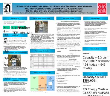
Capital Costs Capacity 6.3 L/s m3/1000L
3600s/hr 24 hr/day 545 m3/day Capital Costs
Capacity 650 354,000 Operating Costs ED
Energy Costs 23,877 kW-hr/d365
d/yr0.07/kW-hr 610,000/yr UV energy costs
are estimated to be 3,300 per year Total Energy
Costs 610,000 3,300 613,300/yr Admin
and Labor Costs 225,680/yr Maintenance Costs
158,500/yr Contingencies Costs 49,900/yr Total
Operational Cost of 1,047,400 /yr
- Samples containing hydrogen peroxide were stored
in a reservoir where initially 15 mL of 2.0 M
sodium bicarbonate solution was added and the
sample was mixed for 30 seconds. - A peristaltic pump with flexible tubing was then
used to re-circulate this water through a 254 nm
ultraviolet light tube and back into the
reservoir for 30 min. - During the time the samples were circulating a
metering pump was used to add 5.0 mL/min of 1.0 M
sodium bicarbonate solution.
Bench Scale Schematic
Acknowledgments
Dr. Harold Walker (Faculty Advisor) BBCM Civil
Engineering Alumni Association Metcalf Eddy
Hydrogen Peroxide Ammonia Evaluation
- Hydrogen peroxide was measured using the
triiodide method. Samples were analyzed with a
Thermo Spectronic Genesys 20 spectrophotometer at
a wavelength of 351 nanometers. - Concentrations of ammonia were analyzed by
measuring mille volts of various solutions with
an Orion Ammonia electrode. The calibration was
conducted by measuring standard ammonia
concentrations of 1000mg/L, 100mg/L, 10mg/L,
1mg/L, and 0.1mg/L.
Recommended
