
x-ray diffraction PowerPoint PPT Presentation
Title: x-ray diffraction
1
(No Transcript)
2
(No Transcript)
3
(No Transcript)
4
(No Transcript)
5
(No Transcript)
6
(No Transcript)
7
(No Transcript)
8
(No Transcript)
9
(No Transcript)
10
(No Transcript)
11
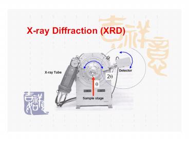
Essential Parts of the Diffractometer
- X-ray Tube the source of X Rays
- Incident-beam optics condition the X-ray beam
before it hits the sample - The goniometer the platform that holds and moves
the sample, optics, detector, and/or tube - The sample sample holder
- Receiving-side optics condition the X-ray beam
after it has encountered the sample - Detector count the number of X Rays scattered by
the sample
12
Instrumentation
- Production of X-Rays
- Collimator
- Monochromator
- Filter
- Crystal monochromator
- Detector
- Photographic methods
- Counter methods
13
The wavelength of X rays is determined by the
anode of the X-ray source.
- Electrons from the filament strike the target
anode, producing characteristic radiation via the
photoelectric effect. - The anode material determines the wavelengths of
characteristic radiation. - While we would prefer a monochromatic source, the
X-ray beam actually consists of several
characteristic wavelengths of X rays.
K
L
M
14
(No Transcript)
15
(No Transcript)
16
(No Transcript)
17
(No Transcript)
18
Braggs law is a simplistic model to understand
what conditions are required for diffraction.
- For parallel planes of atoms, with a space dhkl
between the planes, constructive interference
only occurs when Braggs law is satisfied. - In our diffractometers, the X-ray wavelength l is
fixed. - Consequently, a family of planes produces a
diffraction peak only at a specific angle q. - Additionally, the plane normal must be parallel
to the diffraction vector - Plane normal the direction perpendicular to a
plane of atoms - Diffraction vector the vector that bisects the
angle between the incident and diffracted beam - The space between diffracting planes of atoms
determines peak positions. - The peak intensity is determined by what atoms
are in the diffracting plane.
19
(No Transcript)
20
(No Transcript)
21
(No Transcript)
22
(No Transcript)
23
XRD-Methods
- Laue photographic method
- Braggs X-Ray spectrometer
- Rotating crystal method
- Powder method
24
Laue photographic method
- In his first experiments, Max von Laue (Nobel
Prize in Physics in 1914) used continuous
radiation (with all possible wavelengths) to
impact on a stationary crystal. With this
procedure the crystal generates a set of
diffracted beams that show the internal symmetry
of the crystal. In these circumstances, and
taking into account Bragg's Law, the experimental
constants are the interplanar spacings d and the
crystal position referred to the incident beam.
The variables are the wavelength ? and the
integer number n - n ? 2 dhkl sin ?nh,nk,nl
- Thus, the diffraction pattern will contain (for
the same spacing d) the diffracted beams
corresponding to the first order of diffraction
(n1) of a certain wavelength, the second order
(n2) of half the wavelength (?/2), the third
order (n3) with wavelength ?/3, etc. Therefore,
the Laue diagram is simply a stereographic
projection of the crystal
25
(No Transcript)
26
The Laue method in transmission mode
The Laue method in reflection mode
Laue diagram of a crystal
27
Braggs X-Ray spectrometer
28
- When x-rays are scattered from a crystal lattice,
peaks of scattered intensity are observed which
correspond to the following conditions - The angle of incidence angle of scattering.
- The pathlength difference is equal to an integer
number of wavelengths. - The condition for maximum intensity contained in
Bragg's law above allow us to calculate details
about the crystal structure, or if the crystal
structure is known, to determine the wavelength
of the x-rays incident upon the crystal.
29
X-radiation for diffraction measurements is
produced by a sealed tube or rotating anode.
- Sealed X-ray tubes tend to operate at 1.8 to 3
kW. - Rotating anode X-ray tubes produce much more flux
because they operate at 9 to 18 kW. - A rotating anode spins the anode at 6000 rpm,
helping to distribute heat over a larger area and
therefore allowing the tube to be run at higher
power without melting the target. - Both sources generate X rays by striking the
anode target wth an electron beam from a tungsten
filament. - The target must be water cooled.
- The target and filament must be contained in a
vacuum.
30
Rotating crystal method
31
Most of our powder diffractometers use the
Bragg-Brentano parafocusing geometry.
- A point detector and sample are moved so that the
detector is always at 2q and the sample surface
is always at q to the incident X-ray beam. - In the parafocusing arrangement, the incident-
and diffracted-beam slits move on a circle that
is centered on the sample. Divergent X rays from
the source hit the sample at different points on
its surface. During the diffraction process the X
rays are refocused at the detector slit. - This arrangement provides the best combination of
intensity, peak shape, and angular resolution for
the widest number of samples.
F the X-ray source DS the incident-beam
divergence-limiting slit SS the Soller slit
assembly S the sample RS the diffracted-beam
receiving slit C the monochromator crystal AS
the anti-scatter slit
32
(No Transcript)
33
What is X-ray Powder Diffraction (XRD) X-ray
powder diffraction (XRD) is a rapid analytical
technique primarily used for phase identification
of a crystalline material and can provide
information on unit cell dimensions. The
analyzed material is finely ground, homogenized,
and average bulk composition is determined.
34
- Fundamental Principles of X-ray Powder
Diffraction (XRD) - Max von Laue, in 1912, discovered that
crystalline substances act as three-dimensional
diffraction gratings for X-ray wavelengths
similar to the spacing of planes in a crystal
lattice. - X-ray diffraction is now a common technique for
the study of crystal structures and atomic
spacing. - X-ray diffraction is based on constructive
interference of monochromatic X-rays and a
crystalline sample. - These X-rays are generated by a cathode ray
tube, filtered to produce monochromatic
radiation, collimated to concentrate, and
directed toward the sample. The interaction of
the incident rays with the sample produces
constructive interference (and a diffracted ray)
when conditions satisfy Bragg's Law (n?2d sin
?).
35
- This law relates the wavelength of
electromagnetic radiation to the diffraction
angle and the lattice spacing in a crystalline
sample. - These diffracted X-rays are then detected,
processed and counted. - By scanning the sample through a range of
2?angles, all possible diffraction directions of
the lattice should be attained due to the random
orientation of the powdered material. - Conversion of the diffraction peaks to
d-spacings allows identification of the mineral
because each mineral has a set of unique
d-spacings. Typically, this is achieved by
comparison of d-spacings with standard reference
patterns.
36
- All diffraction methods are based on generation
of X-rays in an X-ray tube. These X-rays are
directed at the sample, and the diffracted rays
are collected. - A key component of all diffraction is the angle
between the incident and diffracted rays. Powder
and single crystal diffraction vary in
instrumentation beyond this.
37
Applications of XRD
- XRD is a nondestructive technique
- To identify crystalline phases and orientation
- To determine structural properties
- Lattice parameters (10-4Å), strain, grain size,
expitaxy, phase composition, preferred
orientation (Laue) order-disorder transformation,
thermal expansion - To measure thickness of thin films and
multi-layers - To determine atomic arrangement
- Detection limits 3 in a two phase mixture can
be - 0.1 with synchrotron radiation
- Spatial resolution normally none
38
- Applications
- X-ray powder diffraction is most widely used for
the identification of unknown crystalline
materials (e.g. minerals, inorganic compounds).
Determination of unknown solids is critical to
studies in geology, environmental science,
material science, engineering and biology. Other
applications include - characterization of crystalline materials
- identification of fine-grained minerals such as
clays and mixed layer clays that are difficult to
determine optically - determination of unit cell dimensions
measurement of sample purity
39
- With specialized techniques, XRD can be used to
- determine crystal structures using Rietveld
refinement - determine of modal amounts of minerals
(quantitative analysis) - make textural measurements, such as the
orientation of grains, in a polycrystalline
sample - characterize thin films samples by
- determining lattice mismatch between film and
substrate and to inferring stress and strain - determining dislocation density and quality of
the film by rocking curve measurements - measuring superlattices in multilayered
epitaxial structures - determining the thickness, roughness and density
of the film using glancing incidence X-ray
reflectivity measurements
40
- Strengths and Limitations of X-ray Powder
Diffraction (XRD)? - Strengths
- Powerful and rapid (lt 20 min) technique for
identification of an unknown mineral - In most cases, it provides an unambiguous
mineral determination - Minimal sample preparation is required
- XRD units are widely available
- Data interpretation is relatively straight
forward
41
- Limitations
- Homogeneous and single phase material is best
for identification of an unknown - Must have access to a standard reference file of
inorganic compounds (d-spacings, hkls) - Requires tenths of a gram of material which must
be ground into a powder - For mixed materials, detection limit is 2 of
sample - For unit cell determinations, indexing of
patterns for non-isometric crystal systems is
complicated - Peak overlay may occur and worsens for high
angle 'reflections'
42
SHIVA.PHARMACIST_at_GMAIL.COM
- THANK
- YOU
Recommended
