
MAESTRO Ship Structural Design PowerPoint PPT Presentation
1 / 127
Title: MAESTRO Ship Structural Design
1
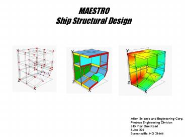
MAESTRO Ship Structural Design
Alion Science and Engineering Corp. Proteus
Engineering Division 345 Pier One Road Suite
200 Stevensville, MD 21666
2
What is MAESTRO?
3
What is MAESTRO?
- is primarily a complete ship structural design
system (though not limited to) for the design of
marine structures. - is for rationally-based design of large,
complex, thin-walled structures. - is primarily for design, but can be used to
analyze existing structures. - provides a highly interactive and intuitive
graphical environment for structural design via
FE modeling/analysis - can model a variety of structures including
monohull ships, multihull ships, offshore
structures, submarines, foundations, etc. - Ship Structural Design, Owen F. Hughes, Ph.D.,
SNAME
4
MAESTRO Main Capabilities
MAESTRO is a complete ship structural design
system
- Rapid Structural Modeling
- Ship-based Loading
- Finite Element Analysis
- Structural Evaluation
- Optimization
- Fine mesh Analysis
- Natural Frequency
5
Main Capabilities-Structural Modeling
6
Main Capabilities-Ship-based Loading
7
Main Capabilities-FE Analysis
Not limited to ship analysis
8
Main Capabilities-FE Analysis
Obtain the stresses throughout the model for all
defined load cases.
9
Main Capabilities-Structural Evaluation
Evaluate the entire ship for all of the different
possible failure Modes for all load cases.
10
Main Capabilities-Optimization
Segregated-ballast Tanker
- Basis Design9708 Cost Units
- Large Scantlings (x3)
- Small Scantlings (?3)
- Optimized Design8477 Cost Units
- Standardizing Sections8664 Cost Units11 Cost
Savings
11
Main Capabilities-Detailed Stress Analysis
Fully integrated fine mesh modeling and analysis
capability. Also, abilityto import FEMAP
detailed models.
12
Main Capabilities-Vibration Analysis
- The 7200 hp escort tug Response experienced
severe vibrations during builders trials - The tug could not operate at its service speed
13
Main Capabilities-Vibration Analysis (contd)
- Full-scale measurements showed the hull vibrating
in the first mode (5.67 Hz) with several hinge
points noted.
14
Main Capabilities-Vibration Analysis (contd)
- Model completed, from paper plans, in 3 weeks.
15
Main Capabilities-Vibration Analysis (contd)
- The eigenvalue analysis closely matched the full
scale measurements (5.47 Hz) and mode shape.
16
Main Capabilities-Vibration Analysis (contd)
- The MAESTRO model was exported to Nastran and a
forced vibration analysis was run using the
engine propulsor excitation forces. - The analysis confirmed the vessels vibration
problem was caused by the propulsor.
17
Main Capabilities-Vibration Analysis (contd)
- MAESTRO was used to re-design the tug until an
acceptable change in the tugs first mode
frequency was reached. - The re-design effort was conducted on-site in
hours, not days or weeks.
18
MAESTRO Main Capabilities
MAESTRO is a complete ship structural design
system
- Rapid Structural Modeling
- Ship-based Loading
- Finite Element Analysis
- Structural Evaluation
- Optimization
- Detailed Stress Analysis
- Natural Frequency
19
6 Basic Aspects of Rationally Based Design
- All 6 are necessary
- All 6 must be balancedand integrated
20
R.B.D.-Modeling of Loads
- All 6 are necessary
- All 6 must be balancedand integrated
21
R.B.D.-Modeling of Loads
Loads are ship-based and easy to apply
- Lightship mass distribution
- Hydrostatic loads
- Stillwater
- Waves
- Tank loads
- Cargo masses
- Forces
- Moments
- Accelerations (6 d.o.f.)
- Pressure loads
- Actual
- Design
- External bending moments and shearforce at ends
of partial models - Boundary conditions
22
R.B.D.-Modeling of Loads LS Mass Distribution
- Selftweight mass
- Scaled structural mass
- Per section
- Per module
- Whole ship
- Individual masses
23
R.B.D.-Modeling of Loads Hydrostatic
- Still water
- Height of WL above global reference point
- Trim Heel angle of waterplane
- Wave pressures (sinusoidal wave)
- Wavelength
- Amplitude
- Phase angle yaw angle
24
R.B.D.-Modeling of Loads Hydrostatic
Hydrostatic loads are appliedand the model is
automaticallybalanced on the chosen waveor
stillwater height.
25
R.B.D.-Modeling of Loads Tanks
26
R.B.D.-Modeling of Loads Cargo masses (Nodal)
- Masses distributed (evenly) among nodes
- Large solid masses (masts, deck, cargo, etc.)
with defined supporting nodes
27
R.B.D.-Modeling of Loads Accelerations
- Translation and rotational accelerations
(with/without gravity) - Center of gravity
- Center of flotation
- Arbitrary point
- This provides the inertial loads for all masses
(lightship and cargo)
28
R.B.D.-Modeling of Loads Pressure
Actual Pressure
- Actual pressures can be constant or vary linearly
across panels - Specified as pressure, LinPress (positive or
negative) - Pressures resulting from a liquid mass with a
designated specific gravity, either as a height
above the bottom of the tank, fraction filled, or
total mass (Volume loading) - This pressure is part of the load matrix
29
R.B.D.-Modeling of Loads Pressure
Design Pressure
- Added to the panel after the FE
solution/considered during evaluation - Design pressures (additive/generic)
- Additive added during evaluation on top of any
other pressure (e.g. ice loads) - Generic are made the lower bound pressure on
the specified panels during evaluation
30
R.B.D.-Modeling of Loads External BM/Shear
- Apply flexural and torsional loads at the ends of
the structural model - Apply preliminary bending moment
31
R.B.D.-Modeling of Loads External BM
The station values (user defined) are displayed
and can be easilly cut and pasted to
MS-Word/Excel.
32
R.B.D.-Modeling of Loads External Shear
The station values (user defined) are displayed
and can be easilly cut and pasted to
MS-Word/Excel.
33
R.B.D.-Modeling of Loads Boundary Conditions
- Restraints
- Normal (6 d.o.f.) rigid body motion
- Automatic centerplane (for half models) for
symmetric or asymmetric loads - Other BC (External Loads)
- Vertical/horizontal BM and shear
- Torsional moment
34
R.B.D.-Modeling of Loads Automatic Balancing
35
R.B.D.-Structural Response Analysis
- All 6 are necessary
- All 6 must be balancedand integrated
36
R.B.D.-Structural Response Analysis
Individual modules are joined interactively to
create the complete model.
37
R.B.D.-Structural Response Analysis
- Module Definitions
- Reference/Opposite Ends
- Section Spacing/Number
- Endpoints
- Strakes
- Stiffener Layout/Spacing
38
R.B.D.-Structural Response Analysis
- Creating Modules Endpoints (Nodes)
- Geometry via drawings
- FastShip
- Rhinoceros
- GHS
39
R.B.D.-Structural Response Analysis
- Creating Modules Strakes (Elements)
- Strakes (combination of elements)
- Quads, triangles, etc.
- Compounds
- Scantling definition
40
R.B.D.-Structural Response Analysis
- Stresses in stiffened panels
- Local bending of frames and girders
- Plate and the stiffener flange
- Combination of global and local loads
- Beam (frames/girders) moments and stresses
- Ends
- Middle
41
R.B.D.-Structural Response Analysis
MAESTRO Version 8.0.0 ANALYSIS JOB
31-AUG-98 PAGE
390 MODULE DATA CREATED BY MAESTRO MODELER FOR
MAESTRO VERSION 7.1
SECTION 19 SIGX
4.44 SIGY 1.79 TAU 5.53
PRESSURE 0.00 SIGVM 10.3 ASIGGP1
2.69 ASIGGP2 6.23 BSIGGP1 2.65
BSIGGP2 6.19 SIGPX1 2.67 SIGPX2
6.21 SIGPYB 1.28 SIGPYA 2.31
MEMBRANE (MIDTHICKNESS) PLATE STRESSES AT
NODES 2.65 1.42 5.05 2.69
2.45 5.61 6.23 2.17 6.01
6.19 1.14 5.45 STRESSES AT
CENTER MEMBRANE 4.44 1.79 5.53 B.M.stiff
0.976E06 B.M.tran -0.733E05 Mtwist
0.229E06 TOTAL, PLT 3.32 0.00 0.00
TOTAL, FLNG 5.59 TOTAL (MEMB. BEND.)
PLATE STRESSES AT GAUSS POINTS 2.35 1.58
5.26 2.37 2.17 5.58 4.30
2.01 5.81 4.28 1.41
5.48
- Stresses are reported in greatest detail in the
output text file (filename.OUT) - All of the stresses are reported here (depending
upon the evaluation level)
42
R.B.D.-Structural Response Analysis
- Stresses are also reported in the GUI, which
allows for dynamic querying of particular areas
and elements - This information can be echoed to the output
window
43
R.B.D.-Structural Response Analysis
The structural response analysis provides stress
and deflection information about the entire vessel
44
R.B.D.-Structural Response Analysis
MAESTRO Verification Procedure
- QUAD4 and hybrid beam elements have been verified
against theory and other FE codes (MSC-Nastran
and ABAQUS) - QUAD4 Verification
- Tested against standard test problems published
by MacNeal and Harder (A Proposed Standard Set
of Problems to Test Finite Element Accuracy,
Finite Elements in Analysis and Design 1, pp.
3-20, 1985) - Patch Test
- Cantilever Beam Test
- Curved Beam Test
- Twisted Beam Test
- Rectangular Plate Test
- Scordelis-Lo Roof Test
- The results show either similar or better level
of accuracy as the results from Nastran or ABAQUS - Beam element
- MAESTRO obtains an exact solution for maximum
displacement with two elements (the minimum
possible) - MAESTRO obtains and exact solution for maximum
bending moment with a single element - Complete results are found in the MAESTRO
Verification Manual
45
R.B.D.-Limit State Analysis
- All 6 are necessary
- All 6 must be balancedand integrated
46
R.B.D.-Limit State Analysis
47
R.B.D.-Limit State Analysis-Module Level
48
R.B.D.-Limit State Analysis-Member Level
49
R.B.D.- Limit State Analysis Theory
- The formulation of MAESTROs limit states is
covered in Hughes, Ship Structural Design A
Rationally Based, Computer-Aided, Optimization
Approach, published by SNAME - An overview of all limit states is given in the
MAESTROs manual.
50
R.B.D.- Evaluation
- All 6 are necessary
- All 6 must be balancedand integrated
51
R.B.D.-Evaluation Formulate Constraints
52
R.B.D.-Evaluation Strength Ratio
Evaluation of the limit states is based upon the
strength ratio
The strength ratio can vary from zero to
infinity, which is not useful for driving
optimization, so we use an adequacy parameter
53
R.B.D.-Evaluation Adequacy Parameter
The adequacy parameter, g
This parameter varies from -1 to 1. Zero
indicates that the structure, under the defined
loads, is optimum for that particular limit
state. Negative values indicate that the
structures response, with the user defined
safety factors, exceeds the limit state.
54
R.B.D.-Evaluation General notes
- Evaluation is automatic - all structural members
are evaluated to the factors of safety chosen by
the user - Either the DNV Steel Ship or the HSLC Rules
factors of safety can be automatically applied if
desired - Different factors of safety can be specified for
all collapse limit states and for all
serviceability limit states, or specified on a
limit state-by-limit state basis. - In addition to the strakes, frames, and girders
which receive full evaluation... - Additional panels, triangles, and additional
beams receive limited evaluation, - Struts and pillars are evaluated for Euler
buckling
55
R.B.D.-Evaluation
The entire structure can be viewed at one time
56
R.B.D.-Evaluation
or only those members who have failed can be
shown (negative adequacy)
57
R.B.D.-Evaluation
Individual members can then be queried to
determine their adequacy parameters and stresses.
This information can be echoed to the output
window.
58
R.B.D.- Optimization Objective
- All 6 are necessary
- All 6 must be balancedand integrated
59
R.B.D.- Optimization Objective
60
R.B.D.- Optimization Objective Cost
61
R.B.D.- Optimization Objective Scantling Limits
- FUNCTIONAL hglt 0.5m
- e.g. constraint on web height for overhead
clearance - LOCAL hslt 30 tw
- e.g., local buckling of stiffener web
- FABRICATION hs 10 lt 0.3 hf
- e.g., cutouts in frames
62
R.B.D.- Optimization Objective Scantling Limits
- The user defines the desired limits on the
scantlings (left) as well as proportional limits
on plating, stiffeners, and beams (above)
63
R.B.D.- Optimization Objective
- All 6 are necessary
- All 6 must be balancedand integrated
64
R.B.D.- Optimization
65
6 Basic Aspects of Rationally Based Design
- All 6 are necessary
- All 6 must be balancedand integrated
66
Examples of MAESTRO Users
- CLASSIFICATION SOCIETIES SAFETY ORGANIZATIONS
- American Bureau of Shipping
- Bureau Veritas
- Canadian Coast Guard
- China Classification Society
- Croatian Register
- Lloyds Register of Shipping
- Polish Register of Shipping
- Registro Italiano Navale (RINa)
- U.S. Coast Guard
- NAVIES
- Australia, Brazil, Canada,
- Chile, Colombia, Germany,
- India, Italy, Japan, Mexico,
- Netherlands, New Zealand,
- Portugal, Turkey,
- United Kingdom, United States
- DESIGNERS RESEARCH ORGANIZATIONS
- CETENA SpA, Italy
- Designers Planners, USA
- Glosten Associates, USA
- Guido Perla Associates, USA
- IZAR, Spain
- JJMA, USA
- MIT, USA
- Rodriquez, Italy
- VUYK, Netherlands
- SHIPYARDS
- Australian Submarine Corp.
- Bath Iron Works
- Bender Shipbuilding
- Northrop Grumman Ship Systems
- Todd Pacific
67
Applications of MAESTRO
- High Speed Ferries
- Warships
- SWATH Vessels
- Containerships
- Cruise Ships
- Offshore Support Vessels
- Tankers/Bulk Carriers
- Floating Dry Docks
- Barges
68
100m Fast Ferry
Photo and model courtesy of Rodriquez
Engineering, Genoa, Italy
69
Canadian Patrol Frigate
70
U.S. Navy AEGIS Cruisers
71
Amphibious Assault Ship (LHD-1)
72
Patrol Boat Optimization
- Proteus optimized the structural design of a 61m
patrol boat designed to DNVs HS LC Rules
73
Patrol Craft USCG Island Class
74
SWATH Vessels Cracking Investigation
75
T-AGOR 26 (Kilo Moana)
- The natural frequency analysis accurately
predicted the hull mode measured in full scale
trials
76
5500 TEU Containership
77
Project America Cruise Ship
Global and Local Analyses conducted for Lloyds
Register
78
Empress of the North Cruise Ship
- Analysis used to verify the effectiveness of the
superstructure
79
OSV Analysis
- 220 OSV
80
Pipe Laying Vessel Analysis
- Proposed design for a pipe laying vessel
- with two moonpools
81
Floating Dry Dock
Forensic analysis - dock failed at less than
design load
82
BIW Land Level Transfer Facility
A detailed model used global results to determine
localized results
83
MAESTRO 8.6 Graphical User Interface
84
Using the Mouse in MAESTRO
Quick View Menu
Quick Construction Geometry Menu
85
Changing the Model View
- Standard Views (right mouse click or via the View
menu) - Bodyplan, Profile, Plan view
- NorthEast, NorthWest
- SouthEast, SouthWest
- Spin, Pan, Zoom, Fit, Last (right mouse click)
- Heel, Pitch, Yaw View Angles
- All view changing commands have no effect on the
model geometry.
86
Displaying the MAESTRO Model
- Rendering Wire/Solid
- Nodes On/Off
- Shrink Elements
- Black/White
- View Options
87
Displaying the MAESTRO Model
- Set View Part
- Set Current Part
- Parts Tree On/Off
- Output Window On/Off
- Groups Tree
88
Displaying the MAESTRO Model
- Load case selection
- Launch Solver
- Dynamic Query
- Output Window On/Off
- Contour (deformation)
- Animation
89
Displaying the MAESTRO Model View Menu
- Control Bars
- This menu item allows the user to toggle any of
the MAESTRO toolbars on or off. - Options
- This menu item allows the user to control a wide
variety of viewing options including element/node
visibility, rendering algorithms, viewport
layout, etc. Selecting this item opens the View
Options dialog box. - Set View
- This menu item allows the user to set the
current viewing angles and view projection.
Selecting this item opens a cascading submenu
which allows the user to choose from a list of
standard views or specify the view angles at the
command line. - Set Window
- This menu item allows the user to modify the
current view parameters including zooming,
panning, fitting the view, toggling to the
previous view, changing the perspective distance,
and storing and recalling views. - Cutting Planes
- This menu item allows the user to create and
delete cutting planes in the current view. A
user can insert a cutting plane into the model
and specify which side is visible and which is
invisible This can be very useful at times, such
as when wishing to view only the interior of a
full hull model. - Set View Part
- This menu item allows the user to set the
current view part in the active viewport. - System Sign
- This menu item allows the user to toggle the
system sign between plus and minus.
90
Displaying the MAESTRO Model View Menu
- Element Type
- This menu is the default view, showing the
default element colors
91
Displaying the MAESTRO Model View Menu
- Element Wetted
- The Wetted Elements view displays all elements
that have been define as "wetted".
92
Displaying the MAESTRO Model View Menu
- By ID
- This menu allows the user to view the model by
Plate Property, Bar Property, Rod Property,
Material, or Stiffener Layout
93
Displaying the MAESTRO Model View Menu
- By ID
- This menu allows the user to view the model by
Plate Property, Bar Property, Rod Property,
Material, or Stiffener Layout
94
Displaying the MAESTRO Model View Menu
- By ID
- This menu allows the user to view the model by
Plate Property, Bar Property, Rod Property,
Material, or Stiffener Layout
95
Displaying the MAESTRO Model View Menu
- By ID
- This menu allows the user to view the model by
Plate Property, Bar Property, Rod Property,
Material, or Stiffener Layout
96
Displaying the MAESTRO Model View Menu
- By ID
- This menu allows the user to view the model by
Plate Property, Bar Property, Rod Property,
Material, or Stiffener Layout
97
Displaying the MAESTRO Model View Menu
- Plate
- This menu allows the user to view the model by
Element Pressure Side, Volume/Plate Pressure
Side, Stiffener Side, Element Normal Side, and
Corrosion Side.
98
Displaying the MAESTRO Model View Menu
- Plate
- This menu allows the user to view the model by
Element Pressure Side, Volume/Plate Pressure
Side, Stiffener Side, Element Normal Side, and
Corrosion Side.
99
Displaying the MAESTRO Model View Menu
- Edges
- This menu allows the user to view the model by
Free edges (any number of), 3 free edges, or 4 or
more free edges.
100
Displaying the MAESTRO Model View Menu
- Warped Quad
- This menu allows the user to view the model by
Warped Quads. - Aspect Ratio
- This menu allows the user to view the model by a
specified Aspect Ratio range. - Internal Angle
- This menu allows the user to view the model by a
specified element edge Internal Angle. - Between Local X
- This menu allows the user to view the model
between the local X axis and the Global X, Global
Y, or Global Z. - Master/Slaves
- This is currently under development.
- All Modules
- This menu allows the user to view the model by
All Modules. This is useful when the MAESTRO
project consists of global and fine mesh models. - Refresh
- This command allows the user to refresh the
graphics.
101
Displaying the MAESTRO Model Hull Menu
- View Self Weight
- The View Self Weight command under the Hull menu
is used to display the MAESTRO calculated
"modeled" weight. The term "modeled" weight
refers to the weight calculated by MAESTRO based
on the materials and elements that make up the FE
model. As shown below, MAESTRO produces a
display of this weight distribution.
102
Displaying the MAESTRO Model Hull Menu
- View Gross Weight
- The View Gross Weight command under the Hull
menu is used to display the FE model's gross
weight for the selected load case. As shown
below, MAESTRO produces a display of this weight
distribution.
103
Displaying the MAESTRO Model Hull Menu
- View Buoyancy
- The View Buoyancy command under the Hull menu is
used to display the FE model's buoyancy
distribution for the selected load case, as shown
below.
104
Displaying the MAESTRO Model Hull Menu
- View Net Force
- The View Net Force command under the Hull menu
is used to display the FE model's net force
distribution for the selected load case, as shown
below.
105
Displaying the MAESTRO Model Hull Menu
- View Shear Force
- The View Shear Force command under the Hull menu
is used to display the FE model's shear force
distribution, as shown below.
106
Displaying the MAESTRO Model Hull Menu
- View Bending Moment
- The View Bending Moment command under the Hull
menu is used to display the FE model's bending
moment distribution, as shown below.
107
Displaying the MAESTRO Model Hull Menu
- View Torsional Moment
- The View Torsional Moment command under the Hull
menu is used to display the FE model's torsional
moment distribution, as shown below.
108
Displaying the MAESTRO Model Hull Menu
- View H. Net and Shear Force, Bending Moment
- The View H. Net Force, H. Shear Force, and H.
Bending Moment command under the Hull menu is
used to display the FE model's horizontal net
force, shear force, and bending moment
distribution, as shown below.
H. Shear Force
H. Net Force
H. Bending Moment
109
Displaying the MAESTRO Model Hull Menu
- Show Properties
- This menu item echoes all of the model section
properties. Things like Area, Inertia, Neutral
Axes, etc.
110
Displaying the MAESTRO Model Hull Menu
- View Element Long. Eff
- The View Element Long. Eff (longitudinally
effective) command under the Hull menu is used to
display structure that is "effective".
111
Displaying the MAESTRO Model Hull Menu
- View Element Long. Eff
- The View Element Long. Eff (longitudinally
effective) command under the Hull menu is used to
display structure that is "effective".
112
Displaying the MAESTRO Model Hull Menu
- View Izz and Iyy
- The View Izz and View Iyy command under the Hull
menu is used to display the FE model's inertia
properties about the z-axis and y-axis
respectively. - View Area
- The View Area command under the Hull menu is
used to display the FE model's area properties,
as shown below. - View Warping Constant
- The View Warping Constant command under the Hull
menu is used to display the FE model's warping
properties, as shown below. - View Torsional Rigidity
- The View Torsional Rigidity command under the
Hull menu is used to display the FE model's
torsional rigidity properties, as shown below. - View Shear Center
- The View Shear Center command under the Hull
menu is used to display the FE model's shear
center, as shown below.
113
Displaying the MAESTRO Model Hull Menu
- View Neutral Axis
- The View Neutral Axis command under the Hull
menu is used to display the FE model's neutral
center, as shown below.
114
Displaying the MAESTRO Model Hull Menu
- Weight Summary
- The Weight Summary command under the Hull menu
is used to produce weight summary tables in the
Output window, as shown below.
115
Creating a MAESTRO model Stage 1
- Create a new MAESTRO model
116
Creating a MAESTRO model Stage 1
- Job Info
117
Creating a MAESTRO model Stage 1
- Importing our IDF file (if available)
118
Creating a MAESTRO model Stage 1
- Creating Parts
- Frame 4 through Frame 9
- Location X120
- Sections 4_at_30inches and 1_at_33inches
119
Creating a MAESTRO model Stage 1
- Endpoints
- X, Y, Z
- Cartesian and Cylindrical
- Reference and Opposite
- 0, 20.25, 51, bilge, 43.5, deck_at_edge, 51, 0
120
Creating a MAESTRO model Stage 1
- Strakes
- General
- Plating
- Frames
- Girders
- Stiffeners
- Deletions
121
Creating a MAESTRO model Stage 1
- Additional nodes
- Springs
- Rods
- Additional Beams
- Triangles
- Additional Quads
- RSplines
- Compounds
- Stiffener layout
- Materials
- Properties
- Delete
- Quick Creation
- Integrity check
It is good practice to check the integrity of
the model after completing a module. After a
module has been completed it is usually advisable
to make a test run. This requires some further
data boundary conditions, loads and, if any
loads involve acceleration, the definition of
masses.
122
Creating a MAESTRO model Stage 2
- Restraints
- The General tab allows the specification of
whatever restraints (fixed nodal displacements
and/or rotations) may be desired.
As we have modeled only a small portion of the
ship (two modules) the boundary conditions will
be artificial and temporary.
123
Creating a MAESTRO model Stage 2
- Groups
- The Groups dialog is activated by clicking on
the icon or by using the Model/Groups menu
from the Main toolbar. The Groups menu consists
of the items used to create, modify, and delete
different types of groups. This is a multiple
page dialog allowing the user to create groups by
volume, plate, module (Scaled Mass), Section,
Node, Bay, General, and Corrosion. A group is
created interactively by selecting members with
the mouse cursor. These members are displayed in
the list box at the bottom of the groups dialog.
Upon completion of modeling the structure, it is
necessary to model the weight distribution and
other loading aspects Groups will aid in this
task
124
Creating a MAESTRO model Stage 2
- Loads
- The Loads dialog is activated by clicking on the
icon or by using the Load/Create Load menu
from the Main toolbar. A load case consists of
all of the loads which act on the structure at
the same time. Loads which do not act
simultaneously should be placed in separate load
cases (unless their interaction is negligible).
Each load case produces a separate solution for
the nodal displacements, and hence load effects,
in the structure. In the evaluation portion of
MAESTRO, for each possible limit state, the
solutions for all load cases are examined to find
the worst case (lowest adequacy parameter) for
that limit state. A dynamic load case requires
masses and accelerations.
125
Creating a MAESTRO model Stage 2
- Automatic balance
- After defining the initial emergence values in a
particular load case, the user should select
Modify and then close the Loads dialog before
invoking the modeler Load Balance command, via
the balance icon found in the top icon bar.
Selecting this icon will open the balance dialog
shown below. Here the user can define
convergence criteria as well as the number of
iterations. If the user selects the User
Control, as shown below, adjustments to the
Center of Flotation and Heel/Trim Angles can be
made.
126
Creating a MAESTRO model Stage 3
- Post-processing
- MAESTRO provides a large number of Pre and
Post-Processing viewing options that help to make
the FEA process easier. These viewing options
can be divided into five general categories and
are found in MAESTRO's main menu. They are the
View, Restraints, Load, Hull, and Result menus.
In combination with the Dynamic Query
functionality, the user can interact with these
menus to increase FEA productivity, verify model
properties, and review analysis results.
- Black/white
- Animation
- Load selection
- View Options
- Gray On/Off
- Dynamic query
- Contour plot
These are typically used in the post-processing
of the model
127
MAESTRO Documentation/Tech Support
- Documentation
- MAESTRO help manual can be accessed via the
Help/Contents menu item. - Hughes. O. F.,Ship Structural Design A
Rationally-Based, Computer-Aided Optimization
Approach, SNAME - Release Notes are posted for each version release
at http//www.proteusengineering.com/maestroReleas
eNotes.htm - Technical Support
- Email proteussupport_at_alionscience.com
- Web http//www.proteusengineering.com/techsupp.ht
m - Fax 1 (410) 643-7535
- Telephone 1 (410) 643-7496
Recommended
