
CONSTRUCTING A FERRO CEMENT TANK PowerPoint PPT Presentation
1 / 42
Title: CONSTRUCTING A FERRO CEMENT TANK
1
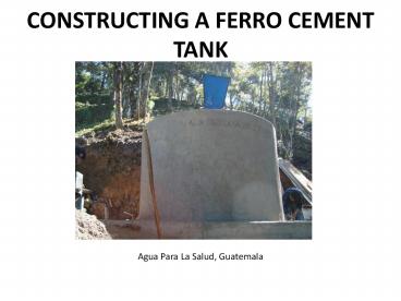
CONSTRUCTING A FERRO CEMENT TANK
- Agua Para La Salud, Guatemala
2
Disclaimer
- The following power point presentation assumes
that individuals using it to construct
ferro-cement tanks have a basic knowledge of
geometry and calculating circumferences and
volumes of spheres so as to select the proper
volume of tank needed for the water system design
being used. Further, the number of entrances and
exits to the tank will again depend on the design
of the system but at a minimum, a water system
tank should have a clean out and overflow entry
of water from the water source and sufficient
exits to serve the distribution system design.
3
Site Preparation and Calculations
4
Materials
- 3/8 reinforcing rods
- 1 ½ galvanised pipe
- Wire
- Mesh
- Door
- 3 inch reinforced rods are welded to the door
frame to attach to the roof structure. - 2 Central Spiders
- 1 ½ galvanized pipe coupling is welded to the
centre of the spider and connecting rods, to
support an 1 ½ galvanised pipe that will support
the roof. - Cement
- Sand
- Gravel
5
Measurements for a 5m3 tank
0.15m
0.15m
6
Calculations for a 5m3 tank
- Height (h) 1.5m
- Diameter (d) 2.50m
- Circumference (c) Pie x d 3.14 x 2.50
- 7.85m
- Spacing of galvanised rods on the frame 0.15m
- Number of rings on the frame
- h / 0.15
- 1.5/0.15
- 10 rings
- Number of galvanised rods moulded to spider
- c / 0.15m
- 7.85/0.15
- 52
- This is the ideal spacing for all tank
sizes in order to provide the frame with
sufficient strength. The larger the tank, the
more important this will be. The pictures of a
5m3 tank within this presentation, may not
accurately depict the necessary spacing required.
7
Site Preparation
- Cut enough room for the entire tank to sit on
solid ground.
8
Tank Floor
Supports for the wall frame are attached to the
base frame .
Second layer of concrete
Base frame
9
- Smooth and compact tank area.
- Construct a wooden mould for the base of the tank
- Ensure boards are held firmly in place
10
- Mark out the centre of the tank
- Make space for the desired piping.
- All tubing inside the tank should be located
under the trapdoor - A standard tank has a minimum of three tubes on
the floor. The first is the inlet pipe from the
water source, the second is an outlet to the
distribution system and the third is used as a
means to clean out the tank. - In this case there is one inlet pipe coming from
the back of the tank and four outlet pipes at the
front of the tank, serving two distribution
systems - All of these tubes will have pvc couplings
attached flush with the floor level, so that the
tubes can be extracted easily. To facilitate the
extraction of these tubes no glue should be used
when inserting them into the couplings. - The overflow tube can also serve as a means of
draining the tank
11
- Over flow and Clear out tube
Trap door
If the water reaches a certain level, it can
overflow through the PVC pipe.
Water
PVC Pipe
Coupling
No glue is used on the coupling or PVC tube, so
that the PVC tube can be extracted easily, in
order to empty the tank.
Elbow
Overflow
12
- Mark onto the boards, a depth of 30cm for the
base. This is the recommended base depth for
tanks up to the size of 10M3 - Use fishing line and a level to ensure that once
the cement is poured, the base is level.
13
- Place rocks over the floor of the tank, leaving a
minimum gap of 10cm by the mould walls for the
cement to fill. - Ensure that the rocks sit fairly level and do not
protrude above the point marked by the fishing
line, 15cm below the top of the boards. - Be careful not to damage the piping. Stuff the
piping with material to ensure that cement does
not accidentally enter.
14
Tank Base
Mould wall
cement
Galvanised rods
15
(No Transcript)
16
- Begin by taking four iron rods, with the ends
bent over. - Tie them together to form a square over the rock
bed.
17
- From the outside in, attach four more rods on
each side of the square, with the ends bent over
the outside frame.
18
- Attach the rods using small pieces of metal wire,
ensuring that once tied, there are no sharp tails
left. - For rods that are parallel to each other, a
simple wrap round and twist with a pair of
plyers, will be sufficient
19
- For rods that are perpendicular to each other use
an iron workers knot illustrated in the
pictures opposite.
20
- Place 4 iron rods diagonally across the inside of
the square so as to strengthen the grid - Place the spider in the centre of the grid and
attach iron rods to its spokes. The number of
rods used will depend on the size of the tank.
21
- The ends of the rods are bent upwards so as to
receive the frame of the tank once the cement has
been poured over the base. - Before fixing the rods in place, ensure that they
are spaced correctly. Ideally they should be
attached at 0.15m intervals.
22
- Finally fix rods on the sides of the square, to
complete the grid. - All rods should be bent down into the space
between the board and the rocks to form the outer
walls of the base.
23
- For the base, use a sand, gravel to cement ratio
by volume of - 2.5 parts gravel
- 2 parts sand
- 1 part cement
- It is not necessary to smooth the tank floor to
perfection, but use fishing wire to ensure that
the floor is level.
24
- Attach the 1 ½ galvanised threaded pipe to the
two spiders, using the 1 ½ pipe couplings on the
spiders. - Once the cement is dry, attach the roof spider to
the centre pole
25
(No Transcript)
26
FRAME
27
- Attach iron rods to the base and roof wheel
- The rods will need to be bent at the desired
height - Using a measuring tape or stick, check that the
rods are the correct distance from the centre of
the tank, before attaching them to the wheel
spokes. In this case, the tank has a radius of
1.25m - When attaching the rods, bend the wheel spokes
down so that they are in line with the iron rod
28
(No Transcript)
29
(No Transcript)
30
- Starting at the base of the tank, bend an iron
rod around the tank to form a ring. In this case
it was necessary to use two iron rods fastened
together by wire. - Once the ring is complete lift it towards the
roof of the tank. Repeat until there are the
desired number of rings.
31
- Before fastening the rings to the frame, ensure
that they are spaced correctly, by 0.15m - The larger the spacing, the less firm the mesh
will be when covering with cement.
32
(No Transcript)
33
- Bend iron rods around the roof of the frame,
again ensuring that they are spaced correctly by
0.15m - Attach the specially designed trap door. It may
be necessary to cut the iron rods to make a large
enough hole.
34
MESH
35
- Wrap the mesh around the tank
- Use small 5cm strips of wire, thread through the
mesh to attach it to the frame at each junction
of the 3/8 reinforcing bar - There will need to be one person threading the
wire through and another inside tying the wire. - It is important to ensure the mesh is tight
against the frame and that it is as free as
possible of dents and bumps.
36
- If two sections of mesh are required to wrap
around the body of the frame, ensure they are
tied together, by threading wire through both
segments. - Finish by attaching segments of mesh to the roof.
37
PLASTER
38
- Use a cement and sand ratio by volume
- 3 parts washed sand
- 1 part cement
- The tank and base will need a total of five coats
of cement. Using a trowel and ensure that the
cement is smoothed over. - Begin on the outside. It will be difficult as
cement will fall through the wire mesh, but once
the first layer has been completed it will become
easier.
39
- Once the first outside layer has dried, it is
possible to begin plastering the inside. - The roof and tank walls will require a total of 5
layers, 2 inside and 3 outside. - It will be more difficult getting the cement to
stick to the roof of the tank. Initially
flicking cement onto the roof and then smoothing
it over can prove effective.
40
Finishing touches
41
- The taps should be housed securely. In this case
a simple cement box is created with cement lid
that can be secured with a padlock. - Normally the exit line would have a valve to turn
off the distribution line to the houses. - If on the side of a hill, ensure that the tank is
secure from potential land slippage. Here a wall
of stones has been built behind the tank. - In temperate climates the tank can be either
above or below ground. However in hot climates
tanks are generally buried underground.
42
(No Transcript)
Recommended
